Machine Components
65
Product Overview
3
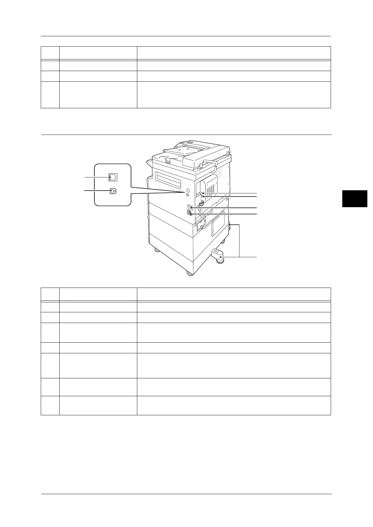
Right Side, Rear
Note • LINE 1 and the TEL connectors are available when the Fax Kit is installed.
• The 10BASE-T/100BASE-TX interface connectors are available when the Network Kit is installed.
11 One tray module cover [B] Open this cover to remove any jammed paper from Tray 2.
12 Tray 5 (bypass) Load paper here. The tray can be extended.
13 Left cover [A] Open this cover to remove any jammed paper.
Note • When the machine works properly, this cover is locked. To open this
cover, make sure to exit Sleep mode and turn the machine's power OFF.
No. Component Description
No. Component Description
1 LINE 1 Connects to a telephone line.
2 TEL Connects to a telephone device.
3 Power switch Switches the power of the machine on and off.
For more information, refer to "Power Source" (P.68).
4 Power cord connector Connects the power cord.
5 Adjusting foot Prevents the machine from toppling over. Move the machine to its
installation site and then rotate this adjuster in clockwise direction until it
touches a floor.
6 USB 1.1/2.0 interface
connector (Type B)
Connect a USB 1.1/2.0 cable.
7
10BASE-T/100BASE-TX
interface connector
Connect a network cable.
 Loading...