Onboard indicators and controls
iRMC
S5
external connectors
INDICATE
CSS
TPM
Slot riser card / slot 1(CPU 1)
Battery
SATA
0-3
Slot riser card / slot 2 (CPU 1)
Slot riser card / slot 3 (CPU 2)
Rear Serial
F
SMB 3
Front
Panel
Micro
SATA
4-7
Internal
USB3.0 /
USB 3
JP3
1
JP2 JP1
1
2
SD
LAN
M.2
SSD1
M.2
SSD2
I
L
G
P
PWR 4
VROC
H
CPU 2 DIMM 2J
CPU 2 DIMM 1M
CPU 2 DIMM 1L
CPU 2 DIMM 2L
CPU 2 DIMM 1J
CPU 2 DIMM 2M
CPU 2 DIMM 2K
CPU 2 DIMM 1K
CPU 2
CPU 1
CPU 1 DIMM 2A
CPU 1 DIMM 1D
CPU 1 DIMM 1C
CPU 1 DIMM 2C
CPU 1 DIMM 1A
CPU 1 DIMM 2D
CPU 1 DIMM 2B
CPU 1 DIMM 1B
CPU 2 DIMM 1R
CPU 2 DIMM 2N
CPU 2 DIMM 2P
CPU 2 DIMM 1P
CPU 2 DIMM 2R
CPU 2 DIMM 1N
CPU 2 DIMM 1Q
CPU 2 DIMM 2Q
H
H
CPU 1 DIMM 1H
CPU 1 DIMM 2E
CPU 1 DIMM 2F
CPU 1 DIMM 1F
CPU 1 DIMM 2H
CPU 1 DIMM 1E
CPU 1 DIMM 1G
CPU 1 DIMM 2G
H
PCH
F
F
F
O
G
SLIMLINE
5 (CPU2)
SLIMLINE
6 (CPU2)
PWR 3
SMB 2
PWR 2
FAN 8
_SYS
FAN 7
_SYS
FAN 6
_SYS
FAN 5
_SYS
FAN 4
_SYS
FAN 3
_SYS
FAN 2
_SYS
FAN 1
_SYS
SLIMLINE 4
(CPU 2)
SLIMLINE 3
(CPU 2)
LC2
SMB 1
P
LC1
SLIMLINE 2
(CPU 1)
SLIMLINE 1
(CPU1)
PWR 1
PWR 5
PWR
ODD
Front VGA
SATA
ODD/8
O
SATA 9
Clear RTC
HDD LED
F
ROC
K
K
K
K
K
K
K
K
OCP 3.0 Slot 1 (CPU1) OCP 3.0 Slot 2 (CPU2)
USB 3.0
Management
VGA
A
B
C
PSU1
PSU2
F
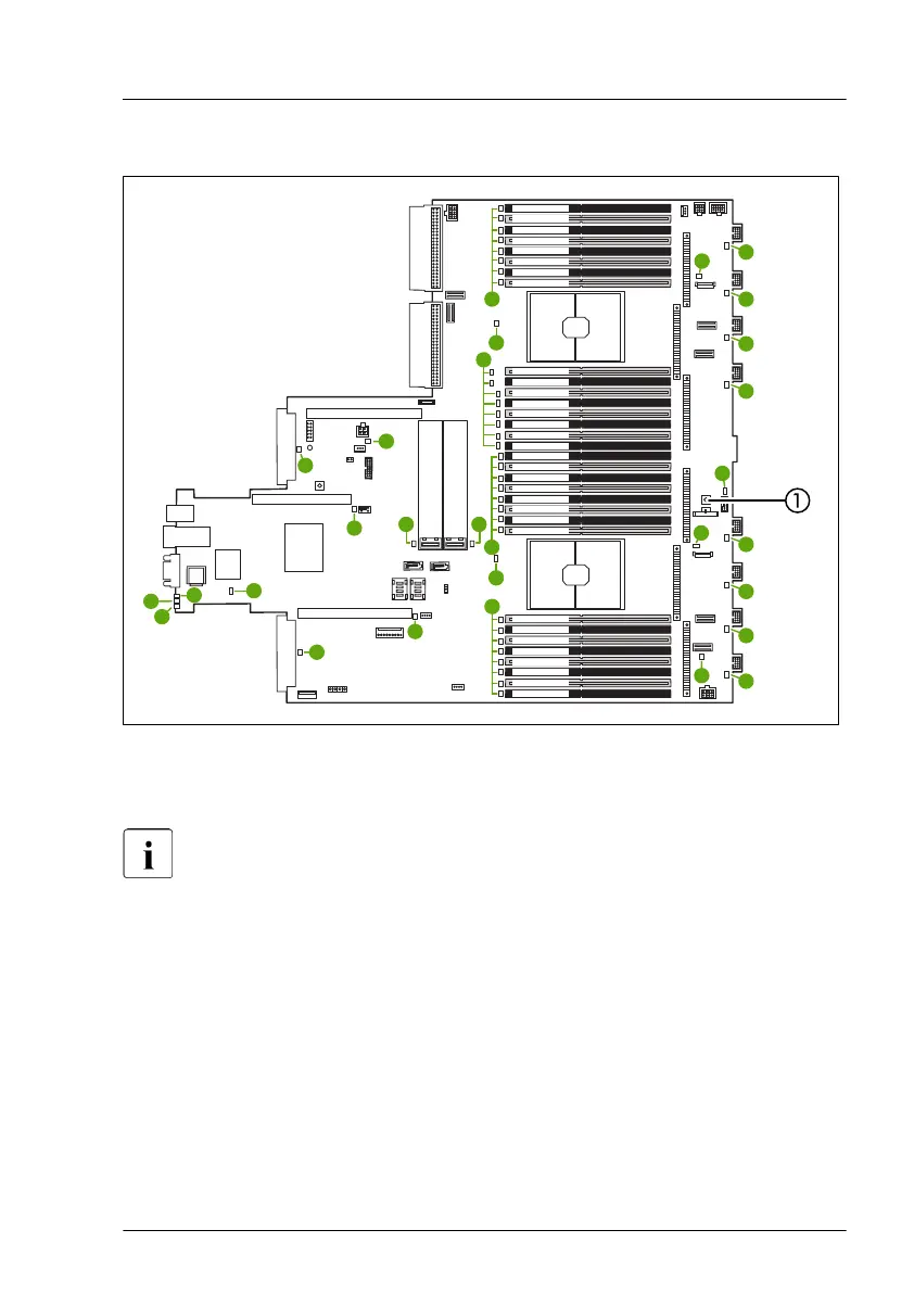
Figure 301: Onboard indicators and controls of the system board D3890
1 Indicate CSS button
LEDs A, B and C are visible from outside on the server rear. All other
LEDs are only visible if the server cover has been opened.
If the server has been powered off (power plugs must be disconnected) it is
possible to indicate the faulty component by pressing the indicate CSS button.
The LEDs have the following meaning:
Appendix A
RX2530 M6 Upgrade and Maintenance Manual 409

 Loading...