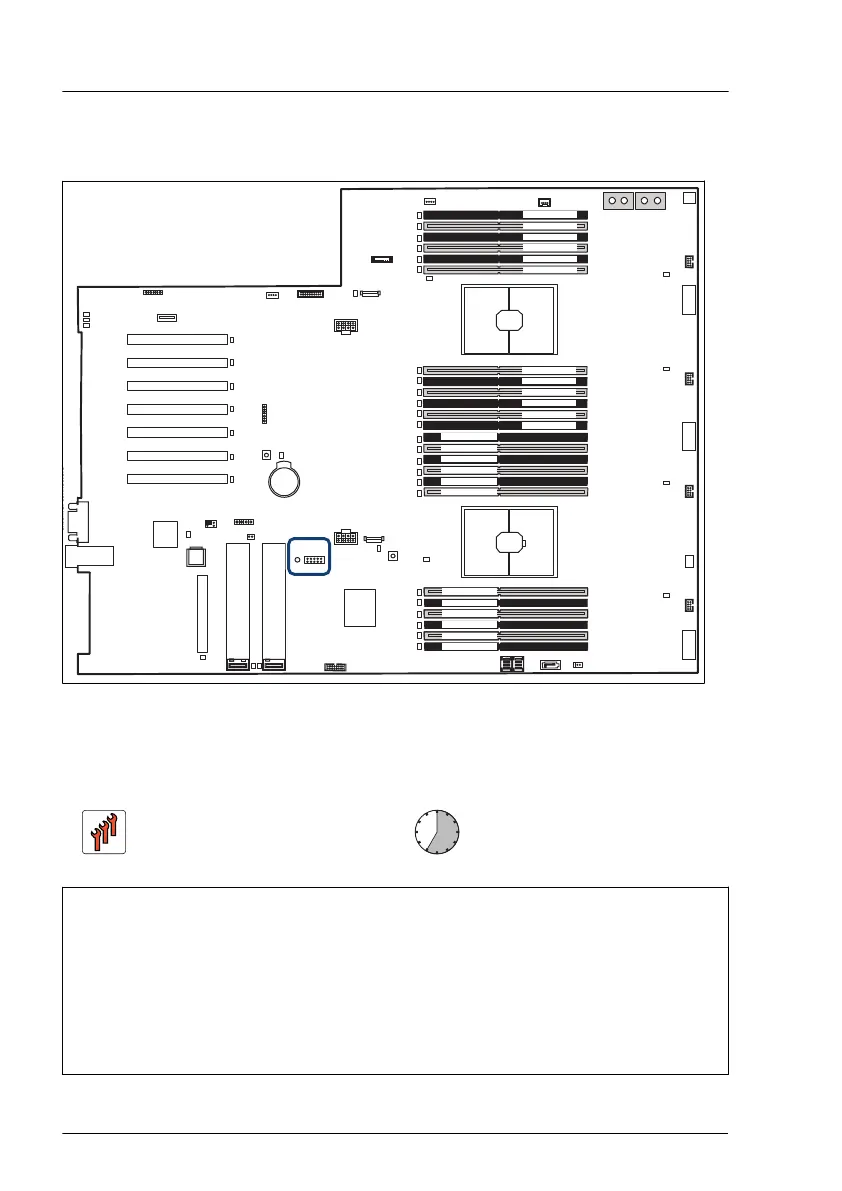
15.4.2 Position of the TPM
Management
LAN / USB 3.0
CPU 2 DIMM 2J
CPU 2 DIMM 1H
CPU 2 DIMM 1G
CPU 2 DIMM 2G
CPU 2 DIMM 1J
CPU 2 DIMM 2H
CPU 2 DIMM 1K
CPU 2 DIMM 2L
CPU 2 DIMM 2M
CPU 2 DIMM 1M
CPU 2 DIMM 2K
CPU 2 DIMM 1L
CPU 1 DIMM 1C
CPU 1 DIMM 2C
CPU 1 DIMM 1B
CPU 1 DIMM 2B
CPU 1 DIMM 1A
CPU 1 DIMM 2A
CPU 1 DIMM 2D
CPU 1 DIMM 1D
CPU 1 DIMM 2E
CPU 1 DIMM 1E
CPU 1 DIMM 2F
CPU 1 DIMM 1F
SATA ODD
Clear RTC
Slot 9 (CPU2)
Micro SD
Battery
iRMC
S5
PCH
Slot OCP module
P30
HDD LED 3
ROC
TPM
INDICATE CSS
Slot 8 (CPU2)
Slot 7 (CPU2)
Slot 6 (CPU2)
Slot 5 (CPU1)
Slot 4 (CPU1)
Slot 3 (CPU1)
M.2
SSD1
M.2
SSD1
M.2
SSD2
HDD LED 2
VROC
LC2
LC1
GPU PWR1
GPU PWR2
JP3
JP2 JP1
1
2
HDD LED 1
OOB_E
PWR4
SATA
0-7
OOB
FAN1
FAN2
FAN3
FAN4
PWR1
PWR2
PWR3
Serial / VGA
Internal
USB 3.0
1
CPU 1
CPU 2
PWR
ODD
Front VGA
USB3
Front Panel
Figure 206: Position of the TPM on the bottom system board
15.4.3 Installing the TPM
Field Replaceable Unit
(FRU)
Hardware: 30 minutes
Software: 5 minutes
Tools: – Phillips PH2 / (+) No. 2 screw driver
–
Bit screw driver
–
TPM bit insert
(*)
(*)
For Japan:
–
TPM module fixing tool (S26361-F3552-L909)
System board and components
332 Upgrade and Maintenance Manual RX4770 M6
 Loading...