GE HEALTHCARE
DIRECTION FQ091013, REVISION 1 VIVID I N AND VIVID Q N SERVICE MANUAL
3-16 Section 3-5 - Preparing for Installation
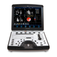
3-5-3-2 Front and Side View of the Vivid i n/ Vivid q N Ultrasound Unit
Figure 3-9 below shows the Vivid i n/ Vivid q N ultrasound unit components that are visible from the front
and side of the ultrasound unit.
1
Display Monitor: tilts up and down.
2
Speakers: Two loudspeakers for Doppler sound
3
Control Panel: Contains the alphanumeric keyboard and the buttons used to operate the
ultrasound unit.
4
Rear Handle
5 Air Vents
6 Probe Ports: Two active probe connectors (one for a pencil probe).
7
ECG Connector
8 ON/OFF Switch
9 Alphanumeric Keyboard and Operation Button
10 Release Latch
Figure 3-9 Front and Side View of the Vivid i n

 Loading...