М
магомедApr 1, 2026
как сбросить настройки на заводские
как сбросить настройки на заводские
как сбросить настройки до заводских
Overview of the ProView 7000™ as a scalable receiver, descrambler, and decoder platform.
Details on TS descrambling and multi-format decoding applications for broadcast.
Lists key features and configuration options of the ProView 7000™ platform.
Describes the ProView 7000™ as a descrambler for digital headend turn around applications.
Explains ProView 7000™ configuration as a multi-format video decoder for SD and HD resolutions.
Overview of DMS as a management system for video distribution networks.
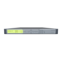
Details the enclosure, front panel, and rear panel of the ProView 7000™ hardware.
Outlines methods for local and remote monitoring and management of the ProView 7000™.
Instructions for initial physical installation and connecting cables to the ProView 7000™.
Procedure for powering on the ProView 7000™ unit and checking the boot process.
Step-by-step guide to setting IP address, subnet mask, and gateway for network configuration.
Overview of configuring and monitoring the ProView 7000™ via front panel or EMS.
Basic configuration steps using the device's front panel interface.
Steps for setting up the Element Management System (EMS) for remote management.
Detailed steps for configuring the ProView 7000™ using the EMS.
Describes the physical components and layout of the ProView 7000™ front panel.
Explains the different types of pages and navigation within the front panel display.
How menu pages display sub-menus and navigate through the interface.
Details on parameter pages showing configurable and read-only settings.
Describes how to edit parameter values using the front panel interface.
Explains radio select pages for choosing options via the front panel.
Detailed configuration of DVB-S/S2 satellite input parameters.
Setup of decoding parameters, including service selection, codecs, and formats.
Configuration of input redundancy, port selection, and descrambling parameters.
Setup of Gigabit Ethernet ports, sockets, and network routing configurations.
Configuration of Conditional Access settings, including BISS and CAM association.
Access to unit configuration options like management port, software version, and licenses.
Creating, activating, renaming, and deleting configuration presets.
How to monitor the operational status of the ProView 7000™ device.
Indicates normal operation with no alarms and green status LEDs.
Displays active alarms, their severity, and descriptions on the front panel.
Detailed information and corrective actions for specific alarm messages.
Reviewing a record of past triggered alarms and exporting them.
Updating the display of elements or devices within the EMS interface.
Displays detailed reception status and signal quality for DVB-S/S2 inputs.
Shows the status of video and audio decoding parameters and elementary streams.
Setting up IP parameters for managing the ProView 7000™ device remotely via EMS.
Minimum hardware and software requirements for running the EMS application.
Steps for installing the EMS application using a web browser.
Procedure to start the EMS application after installation.
How to add a ProView 7000™ device to the EMS for management.
Modifying identification, connection, and SNMP settings for managed devices.
Establishing a connection between the EMS and a ProView 7000™ device.
Testing the network connectivity of a managed ProView 7000™ device.
Closing the connection between the EMS and a ProView 7000™ device.
Deleting a ProView 7000™ device from EMS management.
Accessing the Device Explorer to view input and output stream trees.
Overview of the main components and layout of the EMS graphical user interface.
Basic operations for interacting with EMS GUI elements like boxes and borders.
Updating the display of elements or devices within the EMS interface.
Detailed view of device input/output stream parameters within the EMS.
Details on physical input interfaces like ASI, DVB-S/S2, GbE, and CAM slots.
Managing input streams, programs, tables, and unreferenced PIDs within multiplex inputs.
Configuring multiplex outputs, decoding channels, and stream routing.
Details on physical output ports like ASI and GbE, and decoder module interfaces.
Monitoring and setting properties for various device elements through EMS.
Establishing connections between input streams, programs, and outputs using EMS.
Allocating CAM slots to multiplex inputs or programs for descrambling.
Using wizards for guided cross-connection and decoding channel setup.
Configuring the device for low latency video and audio applications.
Managing connected ProView 7000™ devices via EMS, including backup/restore and presets.
Configuring and monitoring system-level parameters like network, hardware, and communication settings.
Visual indicators of device connection status and alarm severity in the EMS.
Displays active alarms, their severity, time, and description.
Detailed information and corrective actions for specific alarm messages.
Reviewing a record of past triggered alarms and exporting them.
Updating the display of elements or devices within the EMS interface.
Monitoring the reception status and signal quality of DVB-S/S2 input ports.
Viewing the status of video, audio, and service parameters for decoding channels.
Monitoring real-time operational parameters of decoding channels.
Technical specifications for DVB-S/S2 RF inputs, including connectors and frequency range.
Details on DVB-S, DVB-S2, and ASI input interface specifications.
Specifications for ASI and MPEG over IP output interfaces.
Features related to PID filtering, PCR re-stamping, and PSI/SI handling.
Information on DVB-CI slots, CA methods, and supported CAS systems.
Technical details on supported video decoding formats, rates, and audio decoding capabilities.
Specifications for physical video output and audio interface connectors.
Interfaces and protocols used for controlling and monitoring the device.
Lists relevant EMC and Safety standards the device complies with.
Operational and storage environmental specifications like temperature and humidity.
Details on device size, weight, power requirements, and dimensions.
Diagram and description of rear panel ports and connectors on the ProView 7000™.
Pinout details for the RGB port (D-Sub 15).
Pinout details for the ProView 7000™ GPI port (D-Sub 9).
Pinout details for the ProView 7100™ GPI port (D-Sub 15).
Explanation of COM, NC, and NO relay positions for GPI.
Lists features and specifications for different DVB-S/S2 demodulator front-end cards.