Do you have a question about the Harmonic ProView 7000 and is the answer not in the manual?
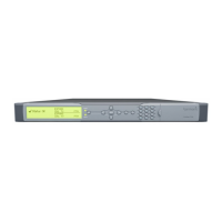
Outlines the wide range of features and available configurations for the ProView 7000 platform.
Provides essential safety guidelines to prevent injury and equipment damage during installation.
Details the requirements for correct and safe operation of the unit's power supply.
Provides instructions for installing the unit into a standard 19-inch rack.
Describes how to connect the ProView 7000 to an AC power supply and ensure proper grounding.
Guides on setting up the IP address, subnet mask, and default gateway for the unit.
Introduces the EMS application for managing ProView 7000 devices via a GUI.
Explains how to configure and monitor the ProView 7000 using the front panel or EMS.
Details the structure and main elements of the EMS Graphical User Interface (GUI).
Explains how to manage ProView 7000 devices by initiating connections and using EMS.
Displays a hierarchical map of input/output ports, streams, programs, and decoders.
Allows monitoring and setting ProView 7000 properties at device and element levels.
Enables monitoring and setting ProView 7000 system-level parameters.
Sets the number of retries for BOOTP and TFTP software upgrade tools.
Presents the hierarchical structure of physical input ports and CAM slots.
Displays the tree structure of multiplex and decoded outputs.
Allows monitoring and setting up decoding channel properties.
Provides the ability to cross-connect input streams to processing functions and outputs.
Details the operation and capabilities of managing the unit via the front panel.
Details the supported video decoding formats, maximum rates, and video processing.
Illustrates the rear panel layout and details the provided ports and connectors.
Lists features for DVB-S/S2 demodulator cards, including modulation and spectral options.
Lists ProView 7000 alarms, their severity, and corrective actions.
Allows performing software version upgrades for selected devices using EMS.