© 2011 Harmonic Inc. 182 ProView 7000 v.2.4, Rev. A
Appendix B
Ports and Connectors
B.1 Overview of Rear Panel Ports and Connectors
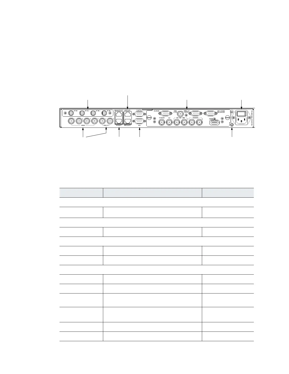
Figure B–1 illustrates a typical ProView 7000 rear panel and Table B–1 details the ports and
connectors provided on the panel.
Figure B–1: ProView 7000 Decoder Rear Panel
Table B–1: Rear Panel Ports and Connectors
Interface Description Connector Type
DVB-S/S2 Interface
RF IN
4 x DVB-S/S2 RF modulated input stream
1
F-Type, 75 Ω
MPEGoIP IN/OUT Interface
MPEGoIP 1 & 2 2 x GbE data ports 100/1000 Base-T, RJ-45
ASI IN/OUT Interface
ASI IN 1, 2, 3 & 4 4 x ASI input stream BNC, 75 Ω
ASI OUT 1 & 2 2 x ASI output stream BNC, 75 Ω
Decoder Audio/Video Outputs
HD-RGB RGB High Definition video output D-Type, 15 pin condensed
GenLock Genlock synchronization input BNC, 75 Ω
Analog Audio 2 x Analog audio stereo output (balanced) D-Type, 15 pin condensed
Digital Audio
Balanced
2 x Digital audio stereo output (balanced) D-Type, 15 pin condensed
CV Analog video output BNC, 75 Ω
CV Monitor Analog video monitoring output BNC, 75 Ω
DVB-S/S2
front-end module
Decoder module, audio/video
ouput interface
ASI in/out ports
Grounding
Jackscrew
AC power connector
and switch
Management
and service
MPEGoIP ports
Control and GPI