23
Setting Measurement Conditions
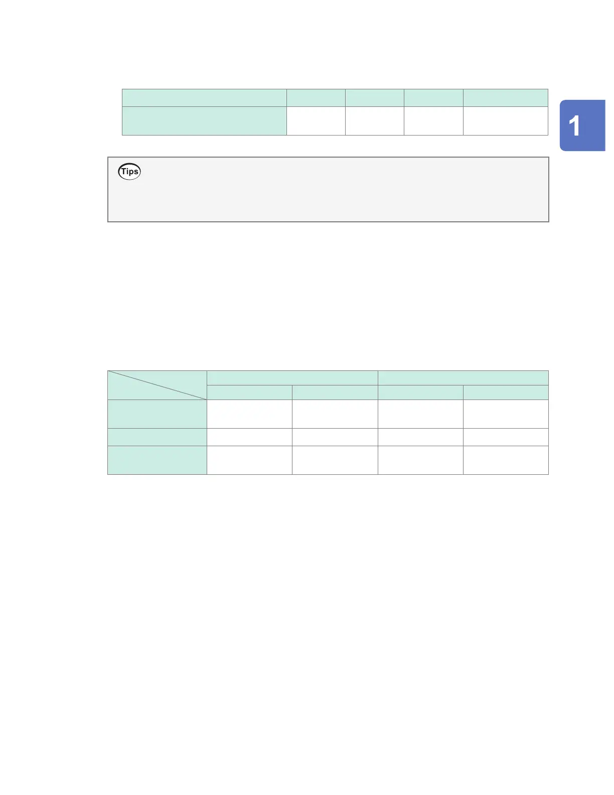
*5: For the U8555/LR8535, the maximum number of channels that can be set varies as indicated in the
following table based on the data refresh interval.
U8555, LR8535 data fresh intervals 10 ms 20 ms 50 ms 100 ms or longer
Maximum number of channels that
can be set
50 100 250 500
• When the data refresh interval is set to a value other than [Auto], it is recommended to use
longer times.
This will allow you to reduce the digital lter’s cuto frequency to eliminate low-frequency noise.
• You can eliminate power supply frequency noise by setting the data refresh interval so that the
[Filter] setting is 50 Hz or 60 Hz.
2
Under [Filter], check the lter’s cuto frequency.
The lter’s cuto frequency will change depending on the data refresh interval setting.
Check the cuto frequency that is displayed for each module.
Relationship between the data refresh interval and the recording interval
• Measurement modules send data to the instrument once each data refresh interval.
• The instrument receives data from measurement modules once each recording interval.
• Even if a measurement module’s data refresh interval is short, it will not be possible to record
waveform peaks if the instrument’s recording interval is long.
Data refresh interval Recording interval
Short Long Short Long
Strength of the power
supply frequency lter
Weak Strong – –
Data volume – – More data Less data
Waveform peaks Easier to capture* More dicult to
capture
Easier to capture* More dicult to
capture
*: If the data refresh interval and recording interval are short.
• For the U8550 to U8553 and LR8530 to LR8533 modules, the longer the data refresh interval,
the lower the digital lter cuto frequency, yielding more eective noise rejection. For more
information about cuto frequencies, see the section about each module’s digital lter in “10.2
Plug-in Module Specications” (p. 310).
• To maximize the eectiveness of the digital lter, congure the [Power frequency lter] setting
according to the power supply frequency in the region where the instrument is being used.
See “7.1 Conguring Settings” (p. 212).
• For modules whose data refresh interval is longer than the recording interval, the rst two data
points will be continuous, and there will be a delay.
Settings and Operation
www.GlobalTestSupply.com
Find Quality Products Online at: sales@GlobalTestSupply.com

 Loading...


