77
Checking Input Signals (Monitor Function)
1.11 Checking Input Signals (Monitor Function)
This section describes how to check input waveforms to verify that settings such as the range and
display range have properly been congured before starting measurement.
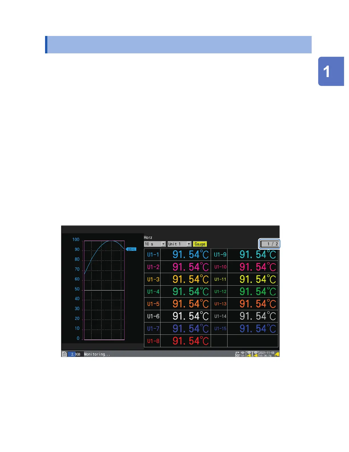
Press the MONITOR key to display waveforms and values on the monitor screen.
Data will be displayed on the screen but not saved in the instrument’s internal buer memory or on
storage media.
(1) Setting the time per division
See the step “Under [Horizontal axis], select the time per division.” (p. 56).
(2) Selecting the module to display
Waveforms for up to 166 channels can be displayed.
(Maximum number of channels: 120 analog, 8 pulse, 8 alarm, and 30 waveform calculation)
(3) Turning the gage on or o
You can choose the channels for which to display a gage.
(4) Switching the channels to display (for modules with 16 channels or more)
Values can be displayed for up to 15 channels on one screen.
(5) Switching display channels for CAN Units
Up to 125 CAN channels can be displayed at the same time.
(1)
(2)
(4)
(3)
The monitor function will terminate when you change the screen display or start measurement.
• The monitor function cannot be used while measurement is in progress.
• The more characters are displayed, the smaller the character sizes become.
You can use the monitor screen displayed during the trigger standby state to activate trigger
forcibly.
See “2.8 Forcibly Activating the Trigger” (p. 132).
Settings and Operation
www.GlobalTestSupply.com
Find Quality Products Online at: sales@GlobalTestSupply.com

 Loading...


