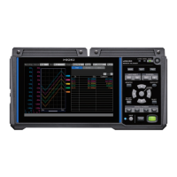
Options Z3230 Wireless LAN Adapter
Z1007 Battery Pack
C1012 Carrying Case
Z2000 Humidity Sensor
2. Input, output, and measurement specications
-1. Basic specications
Number of input
channels
15 channels (Set voltage, thermocouple, humidity, resistance temperature detector, and
resistor for each channel.)
Input terminals
cover
Output terminals M3 screw-type terminal block (1 output, 2 terminals per channel, power supply dedicated
to Z2000 Humidity Sensor, 15 pieces of Z2000 Humidity Sensor can be powered at the
same time)
Measurement target Voltage
Humidity (with Z2000 Humidity Sensor)
Resistance temperature detectors (Pt100, JPt100, Pt1000)
(Connection: 3-wire setup/4-wire setup)
(Measurement current:
(During Pt1000 measurement, setting available when the data refresh interval is
set to 100 ms or longer)
Input type
All channels isolated (The SoL terminals used to connect resistance temperature
detectors and resistors are not isolated as they are shorted for all channels internally.)
A/D resolution 16 bits
Maximum input
voltage
±100 V DC
Maximum channel-to-
channel voltage
300 V DC (The SoL terminals used to connect resistance temperature detectors and
resistors are not isolated as they are shorted for all channels internally.)
Maximum rated
terminal-to-ground
voltage
300 V AC, DC (Measurement Category II)
Anticipated transient overvoltage: 2500 V
Input resistance 10 M
or greater (10 mV f.s. to 2 V f.s. voltage ranges, all thermocouple ranges, all
resistance temperature detector ranges, and all resistor ranges)
1 M
range)
Allowable signal
source resistance
1 k
or less
Reference junction
compensation
Internal/external (user-selectable) (during thermocouple measurement)
Thermocouple wire
break detection
The system will check for wire breaks at the date refresh intervals during thermocouple
measurement.
(Setting not available when the data refresh interval is set to 10 ms.)
Data refresh interval 10 ms*
1
, 20 ms*
2
, 50 ms*
2
, 100 ms, 200 ms, 500 ms, 1 s, 2 s, 5 s, 10 s
*1:
Setting available when thermocouple wire break detection is disabled and no Pt1000
measurement setting is involved.
*2: Setting available when no Pt1000 measurement setting is involved.
www.GlobalTestSupply.com
Find Quality Products Online at: sales@GlobalTestSupply.com

 Loading...