375
Measuring Strain
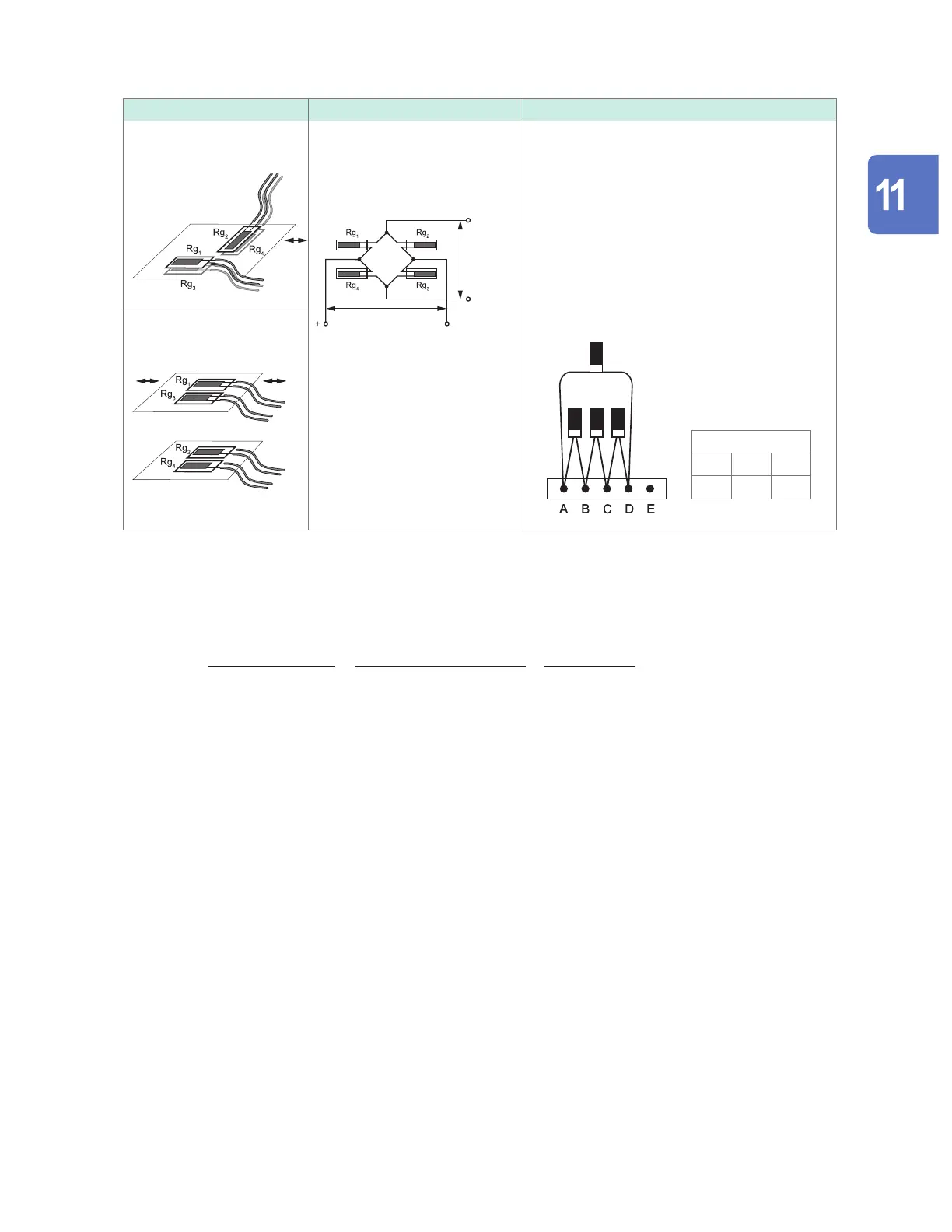
Gage method Bridge circuit diagram Connection to U8554 or LR8534
4-gage method
(perpendicular placement)
Applied voltage
E
Output
voltage
e
Perpendicular placement
e = 2 (1 + Poisson’s ratio) ×
ε
Active dummy method
e = 2
ε
Perpendicular placement
This connection method cancels the eects of
temperature changes of the measurement target.
Use the scaling conversion ratio slope described
below.
1 / {2 × (1 + Poisson’s ratio)}
Active dummy method
This connection method is not aected by
temperature changes of the measurement target
or bending strain. *
2
DIP switch
ON OFF OFF
1 2 3
Rg
4
Rg
2
Rg
1
Rg
3
4-gage method
(active dummy method)
Active gage
Dummy gage
*2: Must be corrected using (2,000,000 × measured value) / (4,000,000 - 2 × measured value). The
scaling function cannot be used to perform correction. Instead, perform correction using the waveform
calculation function.
Example: True strain value if the instrument measures a strain value of 100,000 μ
ε
while using the active
dummy (4-wire) method
ε
i
: True strain value
ε
: Strain value measured by instrument
ε
i
=
(2,000,000 × ε)
(4,000,000 − 2 × ε)
=
(2,000,000 × 100,000)
(4,000,000 − 2 × 100,000)
=
200,000 × 10
6
3,800,000
≈
52632
(με)
Example waveform calculation settings
For footnote *1
W1 = (−1
∗
U1-1) + 1M
W2 = (1M
∗
U1-1) / (1
∗
W1)
W2 indicates the calculation result. The above calculations cannot be combined into a single
setting.
Knowledge and Information
www.GlobalTestSupply.com
Find Quality Products Online at: sales@GlobalTestSupply.com

 Loading...


