394
Text Format
*2: Outputted according to the measurement target as follows:
Voltage (Voltage), thermocouple (Tc), resistance temperature detector (Rtd), humidity (Humidity),
resistance (Resistance), strain (Strain), count (Count), revolving speed (Revolve), logic (Logic),
alarm (Alarm), alarm source (Alarm Source), waveform calculation (Calculation), and CAN.
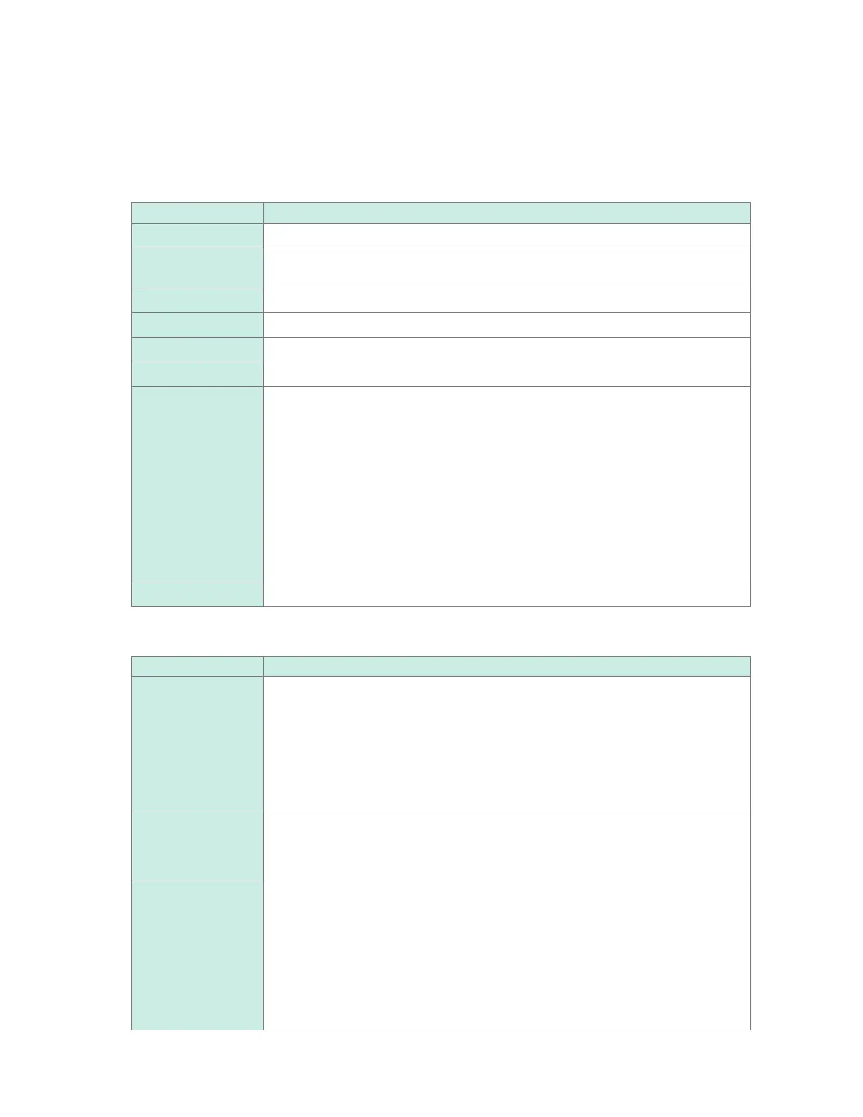
*3: Outputted according to the measured data type as follows.
Data type Output format
Analog Exponential notation (six signicant gures)
Pulse, waveform
calculation
Exponential notation (10 signicant gures)
CAN Exponential notation (10 signicant gures)
Logic 0: Low, 1: High
Alarm 0: Not issued, 1: Issued
Alarm source Hexadecimal notation (blank character when no alarm is issued)*
4
CAN disabled ag Hexadecimal notation
00H: Normal
01H: Unit 1 data error
02H: Unit 2 data error
04H :Unit 3 data error
08H: Unit 4 data error
10H: Remote 1 data error
20H: Remote 2 data error
40H: Remote 4 data error
80H: Remote 5 data error
100H: Remote 6 data error
200H: Remote 7 data error
Event mark 0: No mark assigned, 1 or greater: Marks assigned
*4: Varies depending on the data type
Data type Description
Analog, pulse,
waveform calculation
Alarm onset statuses are outputted with channels assigned to each bit. (CH1
is assigned to the most signicant bit [MSB].) An analog output and waveform
calculation output are represented by eight characters (32 bits); pulse output and
logic output are represented by two characters (8 bits). The letter H is added at the
end.
Example: When U1-1 issues an alarm, the alarm source output is represented by
0x80000000H.
Logic When a channel generates an alarm the output is represented by 1; otherwise,
represented by 0. No letter is added at the end.
Example: When a logic channel issues an alarm, the output is represented by 1.
Break in
thermocouple,
communication error,
low battery
An alarm source output is represented by 12 characters (11 modules and a spare
bit), in which a character (4 bits) is assigned to each module with an alarm status
incorporated.
A break in a thermocouple, communication error, and low battery state are in order
beginning from the MSB (for plug-in modules, broken thermocouple only). The letter
H is added at the end.
Example: When broken thermocouples are found in U2 and U4, the output is
represented by 0x080800000000H.
www.GlobalTestSupply.com
Find Quality Products Online at: sales@GlobalTestSupply.com

 Loading...


