11
Part Names and Functions
No.
Name Description See
1
Display Displays the error number.
p. 114
2
Stand Tilts the RM2611 Electrode Resistance Meter so that the
instrument’s screen is easier to see.
–
3
Test xture connector Connect the RM9005 Connection Cable here.
p. 25
4
Power inlet Connect the included power cord here.
p. 26
5
Main power switch Turns the instrument on and off.
p. 29
6
Maintenance port Not used.
–
7
Maintenance port Not used.
–
8
TEMP.SENSOR terminal Connect the included Z2001 Temperature Sensor here.
p. 28
9
Serial number The 9-digit serial number indicates the year of manufacture (rst
two digits) and the month of manufacture (next two digits). Do not
remove this sticker as the number is important.
–
10
Fuse holder Holds the fuse that protects the measurement circuit. This is not a
customer-replaceable part. Please contact your authorized Hioki
distributor or reseller if you have an issue with the fuse.
–
11
USB port Connects the RM2611 Electrode Resistance Meter to a PC.
p. 27
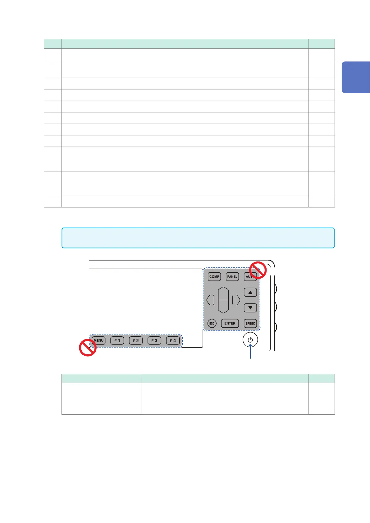
Keys
IMPORTANT
Do not operate the keys on the RM2611 Electrode Resistance Measure (excerpt for the standby key).
Do not use.
Do not use.
Standby key
Name Description See
Standby key Toggles the RM2611 Electrode Resistance Meter’s standby state.
• No light: Power off (no power is being supplied)
• Glowing red: Standby state (power is being supplied)
• Glowing green: Power on
p. 29
1
Overview