82
RM2612 Resistance Calculation Software
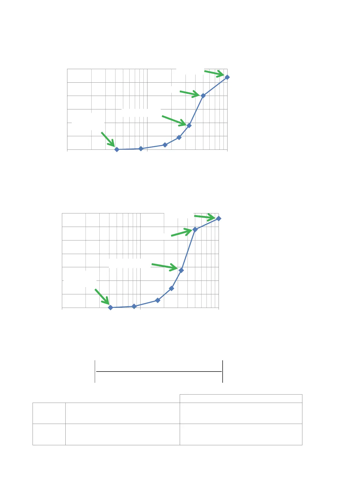
Calculation results with negative electrode representative values
Change in calculated potential values caused by element size
(Potential 120 μm from the probe applying the current)
Potential difference
δ
V
2
10=
−
×
v
v
( ) v ( )
( )
00%
[]
[%]
0.01 0.1
1
0
0.5
1
1.5
2
2.5
3
NORMAL
FINE
SUPER FINE
Minimum
element size
Element size (where NORMAL = 1)
Calculation results with positive electrode representative values
Change in calculated potential values caused by element size
(Potential 120 μm from the probe applying the current)
Potential difference
δ
V
2
10=
−
×
v
v
( ) v ( )
( )
00%
[]
[%]
0.01 0.1
1
0.00
0.50
1.00
1.50
2.00
2.50
3.00
NORMAL
FINE
SUPER FINE
Minimum
element size
Element size (where NORMAL = 1)
3.50
Minimum element size is set internally by Hioki.
The potential difference
δ
V
2
10=
−
×
v
v
( ) v ( )
( )
00%
[]
is dened as follows:
δ
V
2
10=
−
×
v
v
( ) v ( )
( )
00%
[]
Minimum element size
Element size
Minimum element size
Effect of ne volume model area on calculated potential values (reference values)
Parameters of the electrode sheet used as a model
Negative
electrode
NORMAL: 2.0%
MEDIUM: 0.17%
WIDE: 0.04%
Composite layer thickness: 33 μm
Composite layer resistivity: 0.13
Ω
cm
Interface resistance: 0.06
Ω
cm
2
Positive
electrode
NORMAL: 0.61%
MEDIUM: 0.023%
WIDE: 0.003%
Composite layer thickness: 70 μm
Composite layer resistivity: 10
Ω
cm
Interface resistance: 1
Ω
cm
2