86
Output File Formats
2D Potential distribution le format
Header Description
Counter Counter [measurements]
Date Measurement start date
Time Measurement start time
Comment Comment (up to 30 characters)
Range [ohm] Resistance range
Speed Potential measurement speed
TF-Type Fixed value of 1
Composite layer thickness [um] Composite layer thickness [μm]
Collector layer thickness [um] Collector thickness [μm]
Collector resistivity [ohm cm] Collector volume resistivity [
Ω
cm]
Contact check-V Contact check results (32-bit hexadecimal value) (p. 87)
Contact check-I Contact check results (32-bit hexadecimal value) (p. 87)
Potential consistency Potential distribution consistency
Variation-V Potential variability [%]
Error data Number of error data rejections [rejections]
Measurement Time [s] Potential measurement time [s]
Temperature [deg C] Temperature [°C]
RM2611 S/N RM2611 Electrode Resistance Meter serial number
RM2611 Version RM2611 Electrode Resistance Meter rmware version
RM2612 Version PC application version
RM2612 Analysis version Analysis unit version
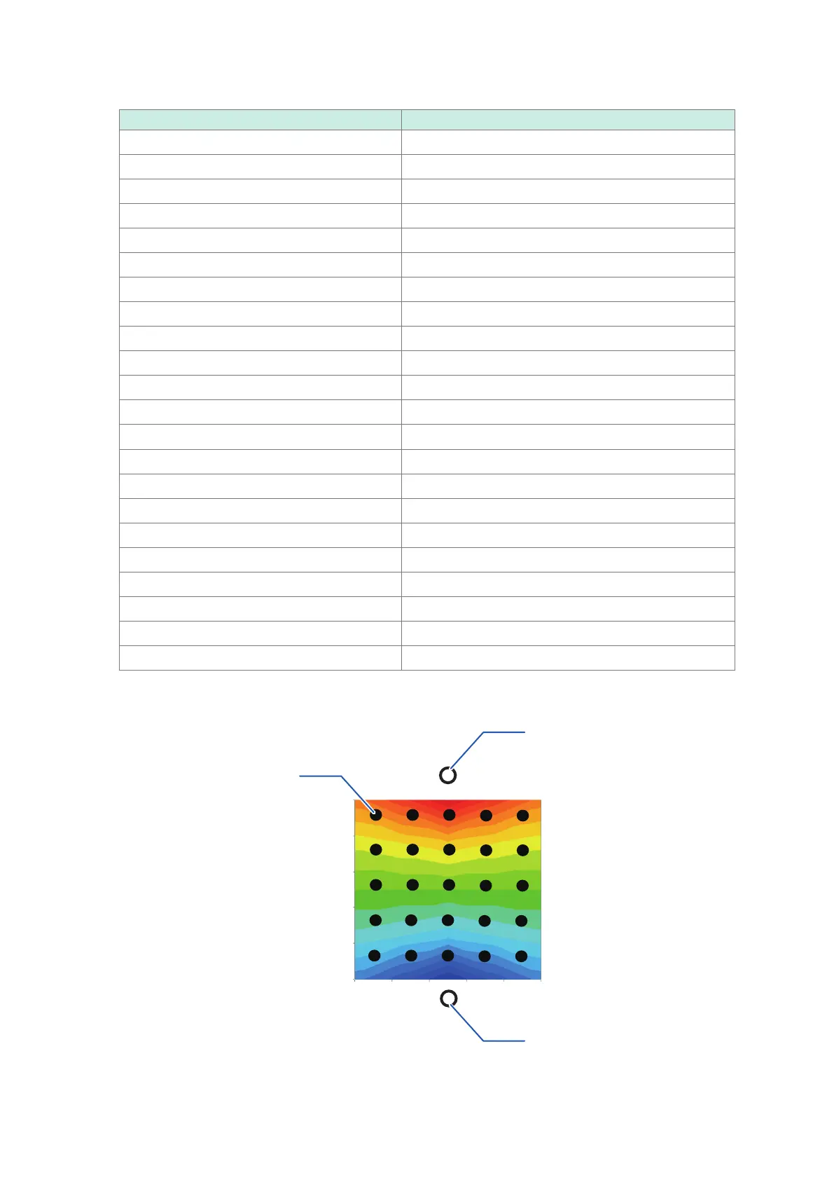
V-Data 5×5 potential data
V-data (5×5 potential data)
Drain probe position
Source probe position
Potential measurement
probe position
(5×5 = 25 locations)