Brevera Breast Biopsy System User Guide
Table of Contents
MAN-04303-002 Revision 006 xi
List of Figures
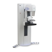
Figure 1: Brevera Breast Biopsy System Overview ....................................................................................................... 7
Figure 2: Label Locations ................................................................................................................................................ 19
Figure 3: System Components (Front, Right) ............................................................................................................... 21
Figure 4: System Components (Back, Left) .................................................................................................................. 22
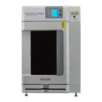
Figure 5: Imaging Cabinet Components ....................................................................................................................... 25
Figure 6: Suction Canister Components ....................................................................................................................... 26
Figure 7: Device Driver Components............................................................................................................................ 27
Figure 8: Metal Parts of the Device Driver ................................................................................................................... 27
Figure 9: Biopsy Needle Components .......................................................................................................................... 28
Figure 10: Biopsy Needle Components - Detailed ...................................................................................................... 29
Figure 11: Tissue Filter Components ............................................................................................................................. 30
Figure 12: System Connections ...................................................................................................................................... 31
Figure 13: Device Driver Connection ............................................................................................................................ 33
Figure 14: Suction Canister Connections ...................................................................................................................... 34
Figure 15: Biopsy Needle and Device Driver Connection .......................................................................................... 35
Figure 16: Tissue Filter Connections in the Tissue Filter Drawer ............................................................................. 36
Figure 17: Tissue Filter Tubing Connection to the Suction Canister ........................................................................ 36
Figure 18: Imaging Panel Controls and Indicators ...................................................................................................... 37
Figure 19: Mode, Arm and Fire Buttons ....................................................................................................................... 38
Figure 20: Startup Screen ................................................................................................................................................ 40
Figure 21: Select an Operator Screen ............................................................................................................................. 41
Figure 22: The Taskbar .................................................................................................................................................... 43
Figure 23: The Select Patient Screen .............................................................................................................................. 44
Figure 24: Add Patient Screens ...................................................................................................................................... 46
Figure 25: The Edit Patient Information Screens ......................................................................................................... 47
Figure 26: Filter Criteria in the Patient Filter Screen ................................................................................................... 48
Figure 27: An Example Procedure Screen .................................................................................................................... 50
Figure 28: Add Procedure Dialog Box .......................................................................................................................... 52
Figure 29: Example, Two Images Selected for Archive/Export ................................................................................. 54
Figure 30: Example, Two Images Selected for Archive/Export ................................................................................. 55
Figure 31: Example of the Print Screen ......................................................................................................................... 56
Figure 32: Setup Screen ................................................................................................................................................... 59
Figure 33: Test Screen ...................................................................................................................................................... 60
Figure 34: Test Screen - Arm and Fire ........................................................................................................................... 61
Figure 35: Standby Screen ............................................................................................................................................... 61
Figure 36: Biopsy Screen ................................................................................................................................................. 62
Figure 37: Lavage Screen ................................................................................................................................................ 63
Figure 38: Aspirate Screen .............................................................................................................................................. 64
Figure 39: No X-ray Screen ............................................................................................................................................. 65
Figure 40: Menu Option for Single Chamber Mode ................................................................................................... 66
Figure 41: Prompt for the Single Chamber Tissue Filter ............................................................................................ 67
Figure 42: Single Chamber Tissue Filter ....................................................................................................................... 67