Components and Architecture - I/O Network
28 HC900 Process Controller Installation and User Guide Revision 19
06/14
I/O Network
I/O Expansion Network (C50 and C50S/C70 and C70S CPU only)
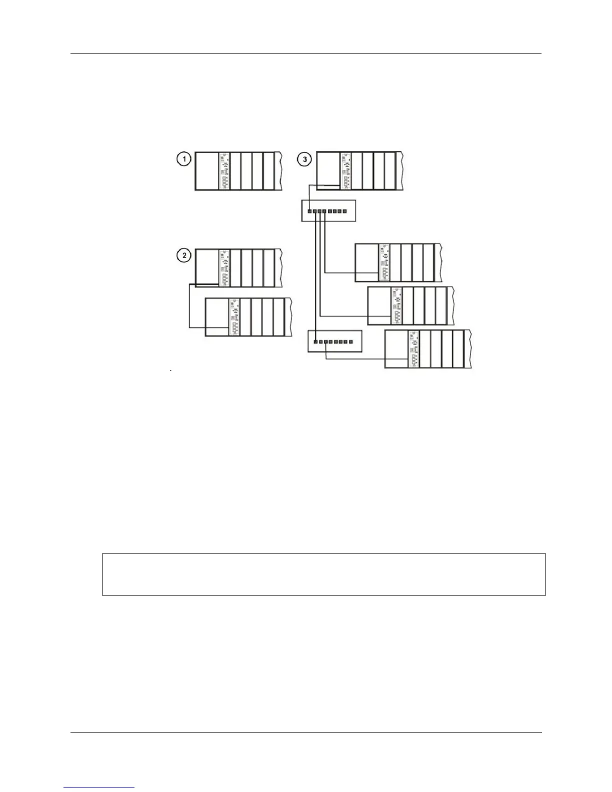
Examples of HC900 Controller I/O expansion configurations are shown in Figure 18.
.
Figure 18 – HC900 Controller Configurations
In any of the racks shown in each controller configuration can be 4-, 8-, or 12-slot versions.
The Ethernet cables for the I/O expansion links are standard shielded Cat 5 IO cables, with standard RJ45
connectors. Each cable segment can be up to 100 meters (328 feet) long.
You can also use fiber optic cable for connections between the controller and a remote rack. Distances up
to 750m (2460 ft.) are possible with one fiber cable. Distances up to 1500m (4920 ft.) are possible with a
fiber switch used as a repeater at the midpoint. (See page 204)
Configuration 1 is the C50/C70 CPU with I/O but no I/O expansion racks.
Configuration 2 shows the C50/C70 CPU with 1 I/O expansion rack. The Ethernet cable connects directly
between the 10Base-T connectors on the C50 CPU Controller Module and the Scanner Module.
ATTENTION:
For 2 or more I/O expansion racks a switch is required. Use only Honeywell recommended switches (part
no. 50008930-001). The total number of switches is limited to 2 in series between a CPU and its scanners.
Configuration 3 shows the C50/C70 CPU with 3 I/O expansion racks. Since there are at least 2 I/O
expansion racks a switch is required. When an Ethernet switch is used to connect to expansion I/O, a cable
goes between the I/O port on the controller to the switch. Two cables go from the switch to 2 scanners. A
third cable goes from the switch to a second switch, which connects to a third remote scanner.
I/O implementation requirements include:
Constructing a configuration file, and loading it into the Controller Module. This file includes I/O
numbering assignments for each I/O Function Block regarding Rack Number, Module Number ("slot"
number, or position in the rack, starting from the left), and Channel Number.

 Loading...


