Communications Installation - Connecting the HC900 Controller to Modbus device(s)
142 HC900 Process Controller Installation and User Guide Revision 19
06/14
Connecting the HC900 Controller to Modbus device(s)
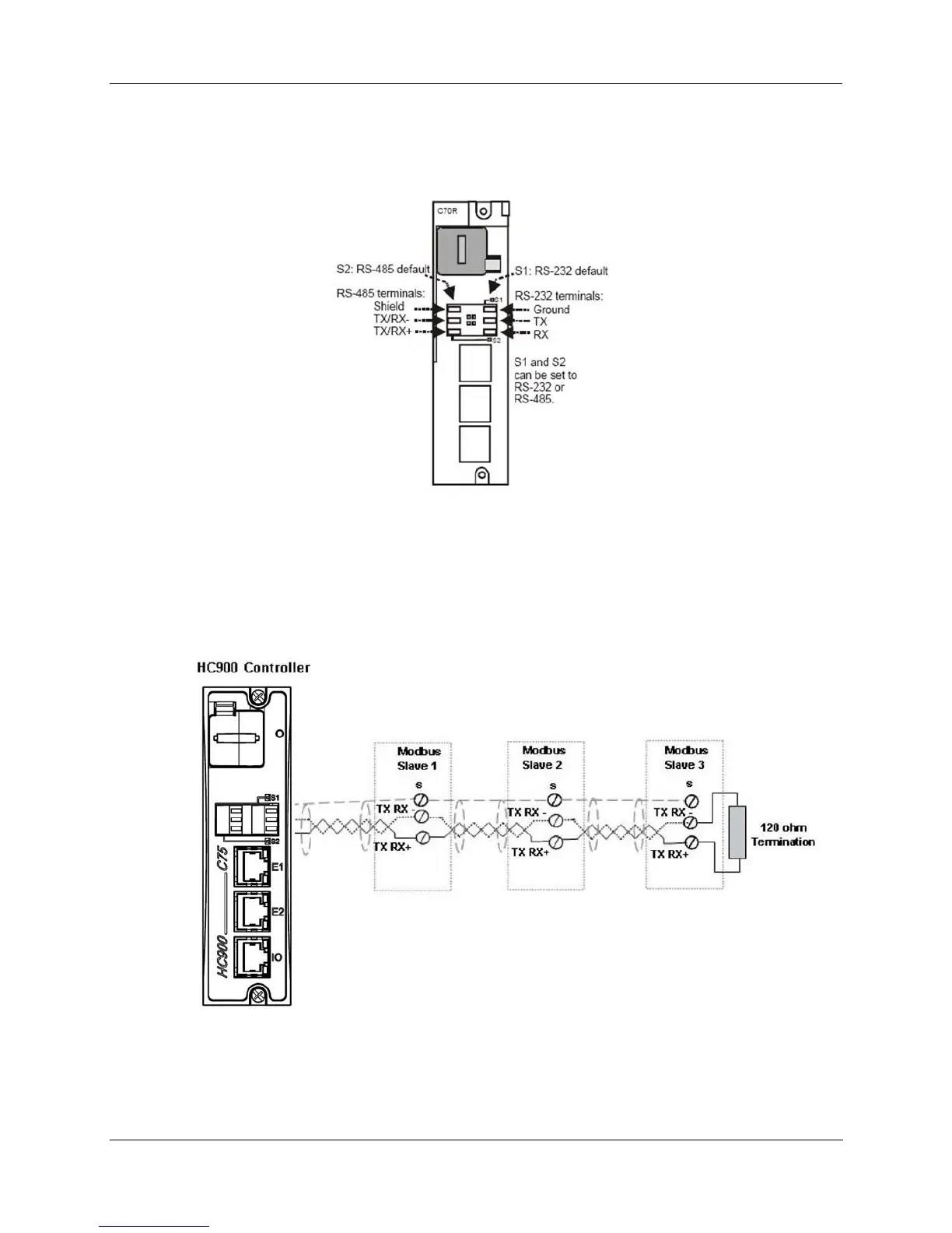
RS-485 Modbus connections
Use HC Designer software to configure the controller’s RS-485 port as a master or slave. Install resistor as
shown for terminated devices except HC900. For terminating HC900, do not install resistor. Instead, set
internal DIP switches for termination (page 36).
When using the HC900 XYR5000 transmitter function blocks and RS-485 serial communications ports,
connect Base Stations to the HC900 controller as shown in Figure 76.
Figure 76 - RS-485 Modbus slave wiring
If the RS-485 network to slave devices is intermittent or fails completely over short durations and recovers
after the controller is power cycled, use an external isolator with additional port biasing. See Figure 77.

 Loading...


