Rack Installation - Assemble I/O Expansion Racks
64 HC900 Process Controller Installation and User Guide Revision 19
06/14
Assemble I/O Expansion Racks
I/O Expansion Rack assembly information is given in Table 11.
Table 11 – Assemble I/O Expansion Racks
Step Procedure Comments/References
1
Insert power supply into
left-most slot in the I/O
rack. See Table 9 steps 1
and 2 for wiring details.
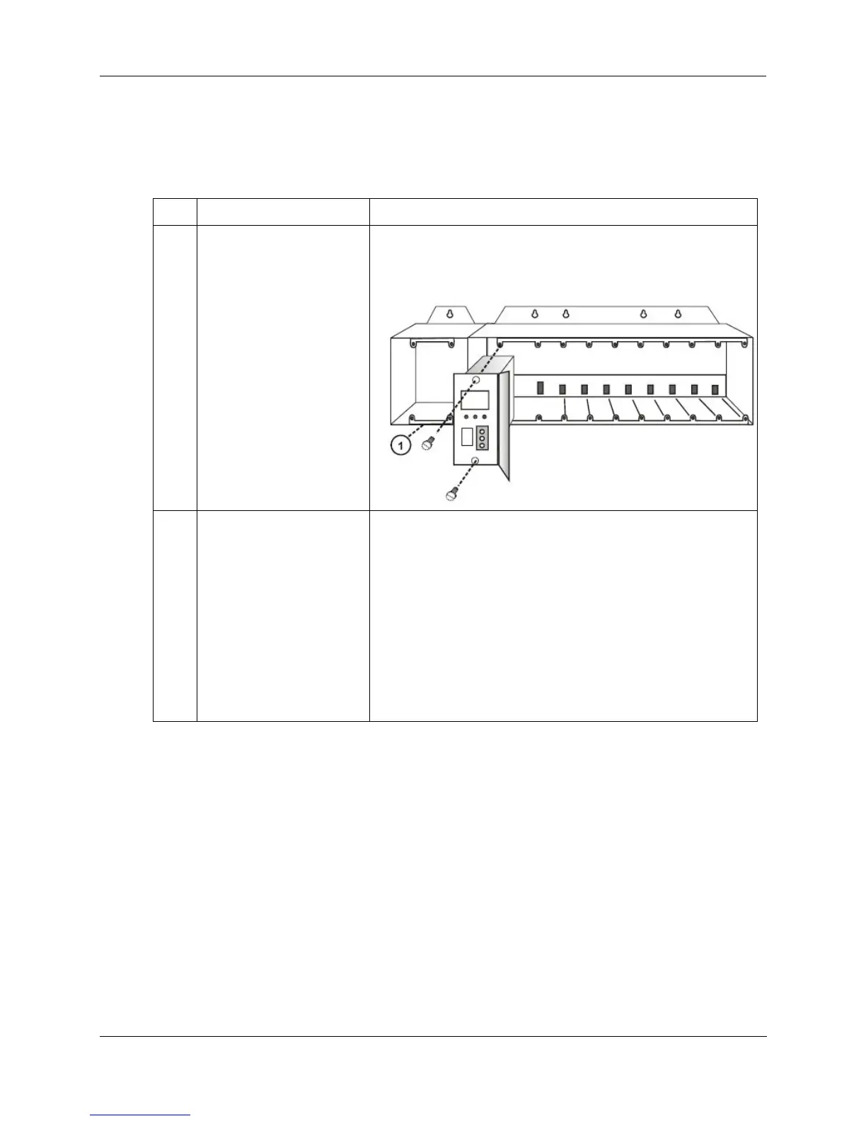
If using redundant power, your I/O rack will contain a second
smaller compartment, see 1 in the following figure. Insert first
power supply in the larger compartment as shown, to the
immediate right of the plate dividing the two compartments.
2
Redundant Power
(optional):
Insert the second power
supply in the left side of
the smaller compartment,
see 1 in figure above. See
Table 10 steps 1 and 2 for
details.
Insert the PSM between
the 2 power supplies.
Fasten it in place with
screws at top and bottom.
See 1 in figure above. See Table 9 steps 1 and 2 for details.

 Loading...


