I/O Module Installation and Wiring - I/O Terminal Block Wiring Diagrams
Revision 19 HC900 Process Controller Installation and User Guide 105
06/14
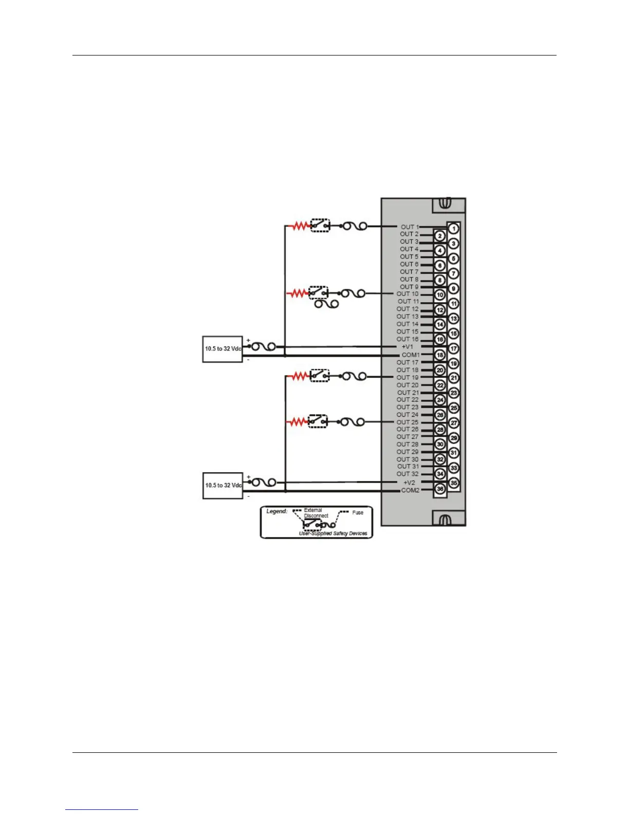
32 point DC Output Wiring
The DC digital Output module provides 32 externally powered outputs in 2 groups of 16 (Figure 58). The
outputs are high side switching (current sourcing) type. Over-current protection is provided for each
channel, in 4 groups of 8 channels. In case of short circuit for any output channel, that whole group of 8 is
switched off. Power cycling is not required to reset the module.
A green LED on the module provides indication of an ON state for each output.
Requires Low Voltage Euro style 36-terminal terminal block.
Figure 58 – 32 point DC Output Module Wiring
AC Output Module Wiring
The AC Output Module provides eight output circuits. Each output is isolated from the other outputs. An
example of AC output wiring is shown in Figure 59. Specifications for this module and for other modules
are given in the Specifications section of this manual.
Output Loading
Voltage: 85 to 240 Vac
Maximum per output: 2.0A resistive load
Maximum per module: 8.0A

 Loading...


