EasyManuals Logo

Honeywell HC900 User Manual

Honeywell HC900
264 pages
To Next Page IconTo Next Page
To Previous Page IconTo Previous Page
Page #122 background imageLoading...
Page #122 background image
I/O Module Installation and Wiring - I/O Terminal Block Wiring Diagrams
110 HC900 Process Controller Installation and User Guide Revision 19
06/14
Hazardous voltages exist at terminal blocks.
Using switches at field devices disconnect the field wiring from power sources before servicing.
Failure to comply with these instructions could result in death or serious injury.
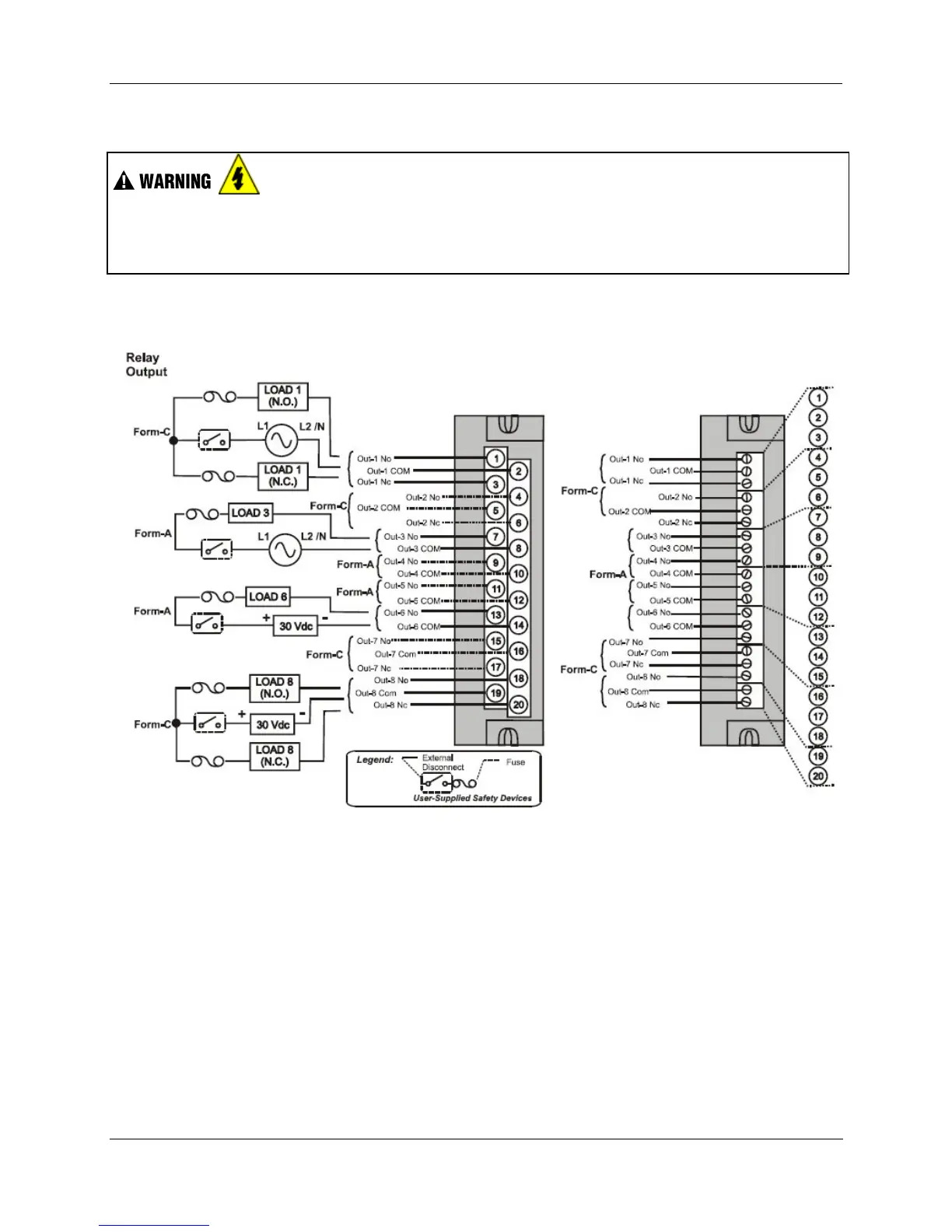
Figure 62 – Relay Output Module Wiring Diagram

Table of Contents

Other manuals for Honeywell HC900

Questions and Answers:

Question and Answer IconNeed help?

Do you have a question about the Honeywell HC900 and is the answer not in the manual?

Honeywell HC900 Specifications

General IconGeneral
SeriesHC900
RedundancyOptional
Programming LanguageFunction Block Diagram, Ladder Logic, Structured Text
InputsAnalog, Digital
OutputsAnalog, Digital, Relay
DisplayOptional
ControlPID, Advanced Control
Power Supply24V DC or 100-240V AC
Storage Temperature-40°C to 85°C
Humidity5% to 95% non-condensing
Communication ProtocolsModbus, Ethernet

Related product manuals