I/O Module Installation and Wiring - I/O Terminal Block Wiring Diagrams
82 HC900 Process Controller Installation and User Guide Revision 19
06/14
I/O Terminal Block Wiring Diagrams
Universal Analog Input Module Wiring
The Universal Analog Input Module has eight inputs, which can include any combination of the following
input types: RTD, TC, Ohms, Millivolt, Volt, or Milliamp. Figure 39 shows wiring examples of each of the
analog input types. An example of wiring for eight TC inputs is given in Figure 41.
Specifications for this module and for other modules are given in the Specifications section of this manual.
ATTENTION
To indicate sensor failure the Analog Input software will output a warning if
thermocouple resistance > 80 ohms. Use appropriate gauge wiring to prevent
inaccurate failure warnings.
Table 15 – Typical Thermocouple resistance in Ohms per Double Foot @ 68 degrees F
AWG No. Diameter
inches
Type K Type J Type T Type E Type S
Pt/ PT110
Type R
Pt/ PT113
Type W5/
W26
Type W/
W26
10 0.102 0.058 0.034 0.029 0.069 0.018 0.018 0.023 0.020
12 0.081 0.091 0.054 0.046 0.109 0.028 0.029 0.037 0.031
14 0.064 0.146 0.087 0.074 0.175 0.045 0.047 0.058 0.049
16 0.051 0.230 0.137 0.117 0.276 0.071 0.073 0.092 0.078
18 0.040 0.374 0.222 0.190 0.448 0.116 0.119 0.148 0.126
20 0.032 0.586 0.357 0.298 0.707 0.185 0.190 0.235 0.200
24 0.0201 1.490 0.878 0.7526 1.78 0.464 0.478 0.594 0.560
26 0.0159 2.381 1.405 1.204 2.836 0.740 0.760 0.945 0.803
30 0.0100 5.984 3.551 3.043 7.169 1.85 1.91 2.38 2.03
Table values are shown as a reference only; actual values may vary. Consult manufacturer specifications.
Isolation
This module has eight inputs, which are isolated except for RTD current sources.
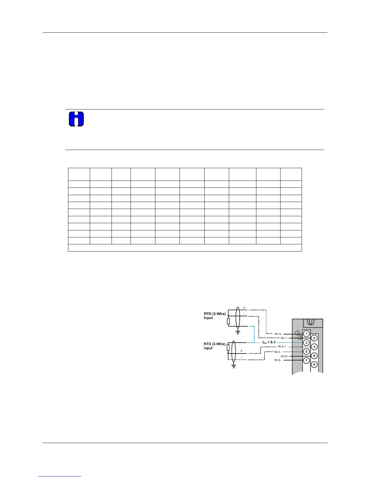
RTD Inputs
RTD inputs share current sources (two RTD inputs per
source), as shown in Figure 38, Figure 39, and Figure
40.
For example, the current source for the RTD input at
channel one (terminals 1 and 2) is terminal 3 (I
RTD
1 &
2). This same current source (I
RTD
1 & 2) is also used
for an RTD input at channel two (terminals 4 and 5).
Figure 38 and Figure 42 show examples of RTD input
wiring (2-wire and 3-wire RTDs). Four-wire RTD
inputs are not available.
Figure 38 – RTD Inputs

 Loading...


