Components and Architecture - Hardware Components
18 HC900 Process Controller Installation and User Guide Revision 19
06/14
Hardware Components
This section contains general descriptions of each of the major components of the HC900 system.
For environmental specifications, refer to the section on Pre-Installation Planning.
HC900 Controller Rack
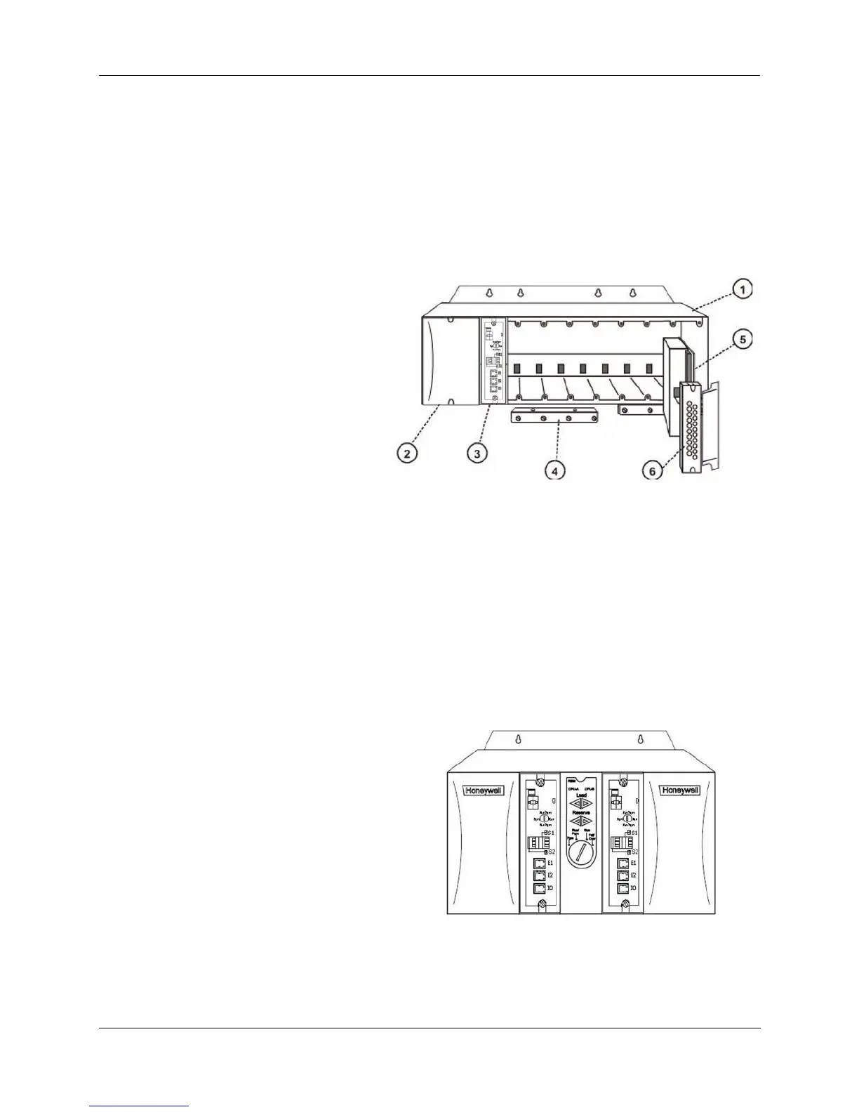
An HC900 Controller ("local rack") is shown in the following figure. As indicated in this figure, the
Controller Rack includes:
1. Rack, available in 4- 8-, or 12-slot
versions
2. Power Supply
3. Controller Module
4. Grounding bars (for I/O wiring;
optional)
5. Input/Output modules.
6. I/O Terminal Blocks
Figure 6 – Controller Rack Components
HC900 Redundant Controller Rack
A HC900 Redundant Controller is shown in Figure 7.
1. Rack
2. Redundancy Switch Module (RSM) . Interface between Lead/Reserve controllers.
3. Lead/Reserve controllers. Two C75 CPUs, designated “CPU-A” (left), “CPU-B” (right).
4. Two 900P02-0001 Power Supplies.
Figure 7 – Redundant Controller Rack Components

 Loading...


