I/O Module Installation and Wiring - Module Placement in Racks
68 HC900 Process Controller Installation and User Guide Revision 19
06/14
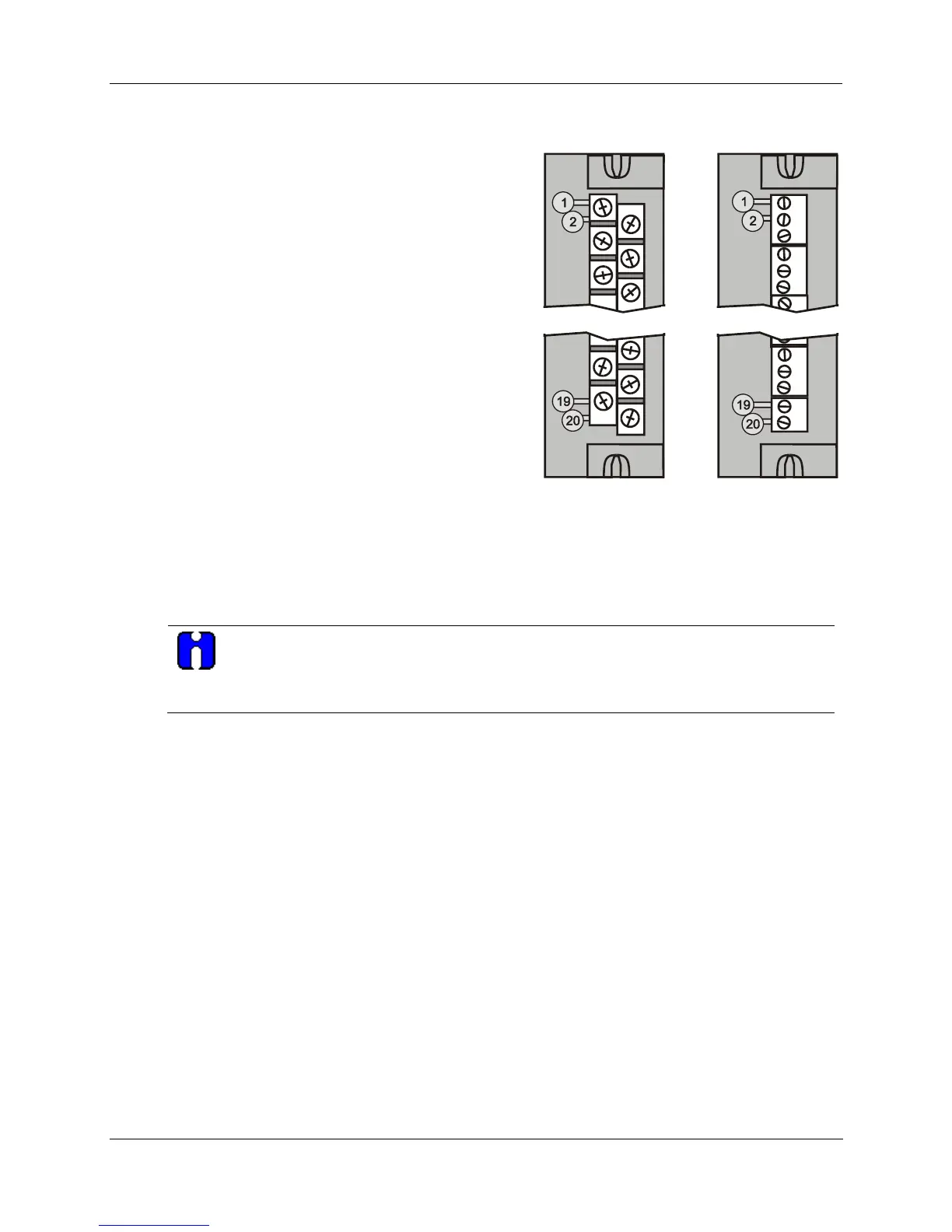
Terminal Block Styles
The terminal block is available in the barrier style, shown
at left in Figure 34, and the Euro style, shown at right.
Not shown: a Euro style with 36 connections is also
available for certain high capacity modules.
Terminal blocks have an embossed numbering “key” that
shows the numbering pattern of the 20/36 connections.
The frame associated with the terminal block has a
transparent hinged door. The hinged door is a tool
secured cover. To open the door, insert a flat screwdriver
into the slot at the top and bottom of the door while
pulling out. The door has molded-in tabs that hold labels,
which are uniquely color-coded to identify each module
type.
Each label is printed on both sides. On the front (visible
when the door is closed) are I/O channel numbers, with
spaces in which tag names can be written. On the back
(visible when the door is open) are wiring patterns for the
type of module located in the slot.
Figure 34 – Terminal Block Styles
The 20-pin, inline connectors at the back of the terminal blocks are universal; that is, any type of I/O
module can be used with either the Barrier style or the Euro style terminal block. The 36-pin Euro terminal
blocks must be used with High Level AI, High Level AO, 32 DI, and 32 DO modules.
ATTENTION
Before mounting terminal blocks in the rack, be sure they are properly keyed to the
module type they will be used with. See I/O Module Installation Procedures, page 74.
Terminal Block Colors and Keying
Both the barrier style and the Euro style are available in two colors (red and black). Black terminal blocks,
which have gold contacts, are used for low-voltage, low-energy signals such as contact inputs and low DC
voltages. Red terminal blocks, which have tin contacts, are used for higher voltages such as 120/240 Vac.
Colors of each Terminal Blocks must correlate to that of the mating header on I/O modules with which they
are used; that is:
• Black terminal blocks, which have gold contacts, are for use with I/O modules that have black headers
and gold pins in the 20-pin connector; these include: Analog Input, 4-channel Analog Output, DC Input,
DC Output, Contact Input, Pulse Input, Pulse Output, Frequency Input, Quadrature Input.
• Red terminal blocks, which have white (tin) contacts, are for use with I/O modules that have red headers
and white- (tin-) contacts in the 20-pin connector; these include: AC Input, AC Output, and Relay
Output.
• 36-pin black Euro terminal blocks, which have gold contacts, are for use with 8-point AO, 16-point AO,
16-point AI, 32-point DI, and 32-point DO modules.
• Terminal blocks may be keyed by the installer to prevent high voltage terminal blocks from being
installed on low voltage modules. See Table 14.
• Any of the color-coded labels will fit into the door of any terminal block. Use care to ensure that all
hardware components match each other, and also match the control strategy in the configuration file.

 Loading...


