Diagnostics and Troubleshooting - Scanner indicators
Revision 19 HC900 Process Controller Installation and User Guide 171
06/14
Scanner indicators
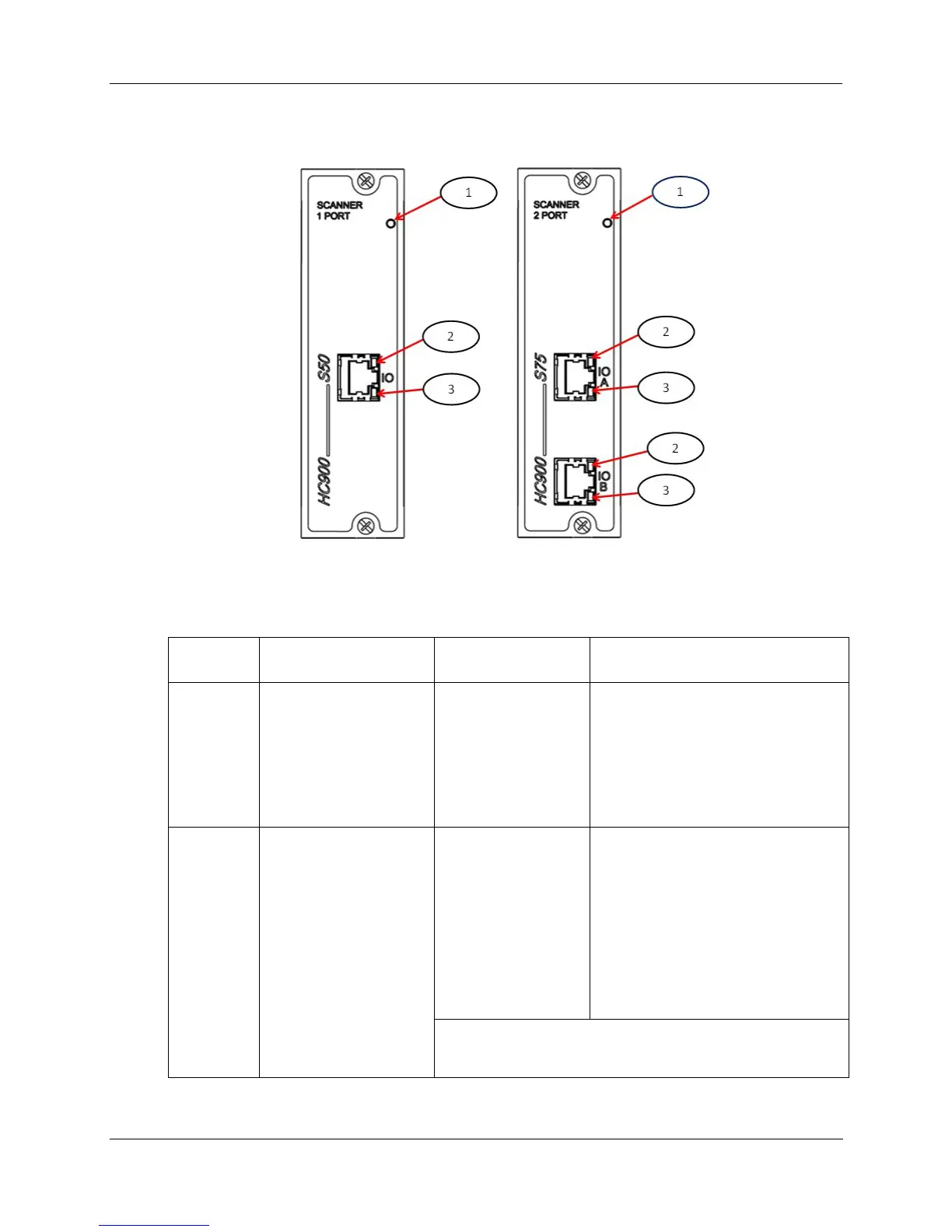
Figure 86 – LED Indicators on Scanners—1 port (left), 2 port (right) (See Table 28)
Table 28 – LED Indications on Scanner Module
Figure 80
item
LED LED State/Color Description
1 Scanner Status Off
Solid Red
Blinking Red
Solid Green
Blinking Green
No power
Failed
(Diagnostic Code; refer to Table 29 -
Scanner LED Diagnostics.)
Startup Mode
Scan Mode
2
3
10Base-T port
XMT (upper LED)
LINK (lower LED)
Green (On/Off)
Green (On/Off)
On while a message is being sent from
the Main CPU; otherwise Off.
On while the Main CPU is receiving a
message. Remains On as long as
host is present; Off when the host is
removed from the link.
NOTE: These LEDs indicate activity on the communication
port, they are controlled by hardware (PHY chip), not by
software.

 Loading...


