I/O Module Installation and Wiring - I/O Terminal Block Wiring Diagrams
96 HC900 Process Controller Installation and User Guide Revision 19
06/14
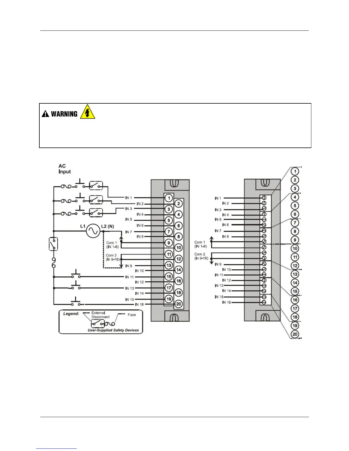
Common Terminals
Two common terminals are provided for each group of eight inputs. Terminals 9 and 10 are connected in
the input module, and terminals 11 and 12 are connected in the module.
Jumper Comb
An optional two-position jumper comb is available as an option (for barrier style terminal blocks only) for
connecting digital common wiring at terminals 9 and 11 or terminals 10 and 12. See Figure 53.
Hazardous voltages exist at terminal blocks.
• Using switches at field devices, disconnect the field wiring from power sources before servicing.
Failure to comply with these instructions could result in death or serious injury.
Figure 52 – AC Input Module Wiring Diagram

 Loading...


