Introduction - Functional Description
Revision 19 HC900 Process Controller Installation and User Guide 9
06/14
Redundancy
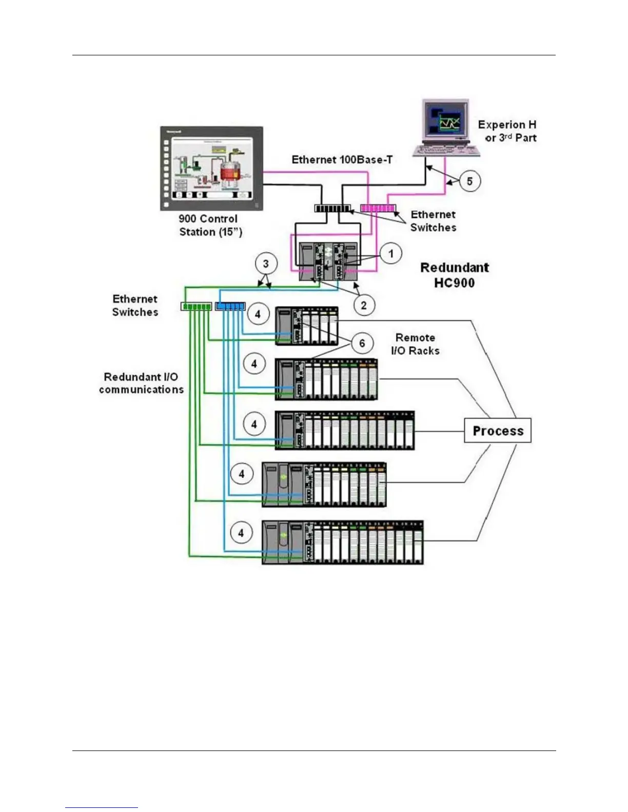
Figure 3 – Single process with redundancies
Redundant CPUs - Redundancy is provided by two C75 CPUs operating in a controller rack; this rack has no
I/O. A Redundancy switch module (RSM) sits between the CPUs.
Redundant CPU Power - Two power supplies, one for each C75 CPU.
Redundant CPU-I/O connection – Each CPU has its own 100 base-T Ethernet physical communication link with
one or more racks of I/O. Multiple I/O racks require Ethernet switches.
I/O racks – 5 racks shown, top to bottom: 4-slot w/1 power supply, 8-slot w/1 power supply, 12-slot w/1 power
supply, 8-slot w/redundant power supplies, 12-slot w/redundant power supplies. A Power Status Module (PSM) is
required with redundant power supplies. High and low capacity power supplies are available.

 Loading...


