Rack Installation - Overview
Revision 19 HC900 Process Controller Installation and User Guide 55
06/14
Rack Installation
Overview
This section contains procedures for installing one or more HC900 Controllers. It is recommended that the
information in this section be reviewed before beginning the installation. Familiarity with the overall
procedure will help to prevent errors and will promote efficiency in general.
Tools Required
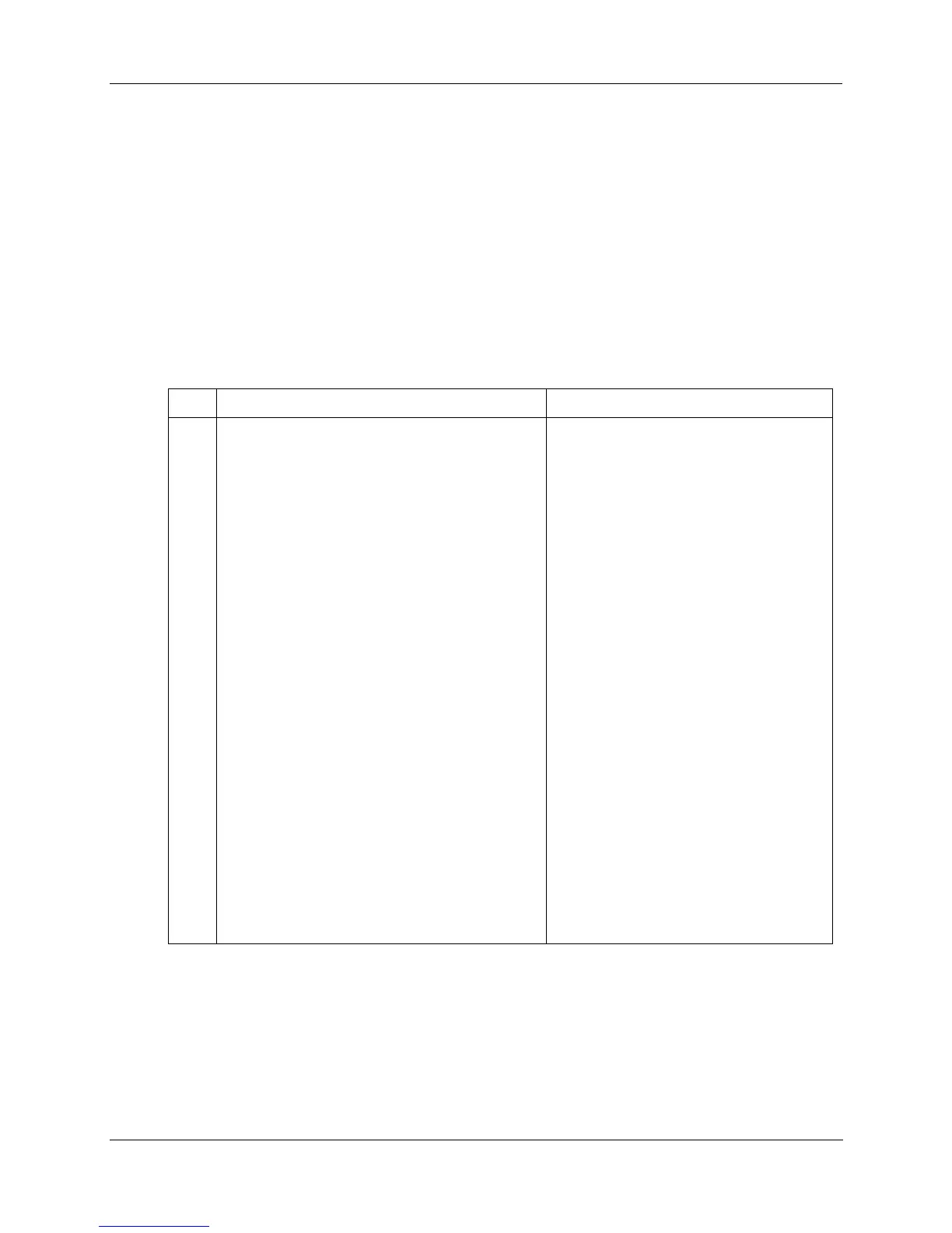
The primary tools required during installation are listed in Table 6.
Table 6 – Installation Tools
Item Description Comments
1
2
3
4
5
6
7
8
9
10
11
Common tools
• Wire strippers
• Crimper
Screwdrivers
• Small flat-tip
• Small/medium flat-tip or Phillips
• Large (long blade)
Other
• Electric drill, with drill bits for #10 or M4
screws, and with drill-bit extender
• Vacuum cleaner, brush
• Pen, ball-point or felt-tip, for entering data on
labels for I/O modules)
• Multi-Meter (Volt/Ohms/Amps)
• Soldering pencil or gun (for attaching filter
capacitors to I/O wiring shields)
Special tools
• Precision meters
For Power Supply and for I/O Wiring
For Terminal Lugs on Power Supply wiring
and on I/O wiring shields
For Euro-style Terminal Blocks
For Barrier style Terminal blocks); also for
captured screws in Terminal Blocks
For use as I/O Module extractor
For rack mounting
For use during and after drilling operations
For entering data on labels for I/O modules
For safety checks and for equipment test
For attaching filter capacitors on I/O wiring
shields
(If required) for testing Analog calibration;
refer to Analog Calibration in this manual.

 Loading...


