I/O Module Installation and Wiring - I/O Terminal Block Wiring Diagrams
Revision 19 HC900 Process Controller Installation and User Guide 111
06/14
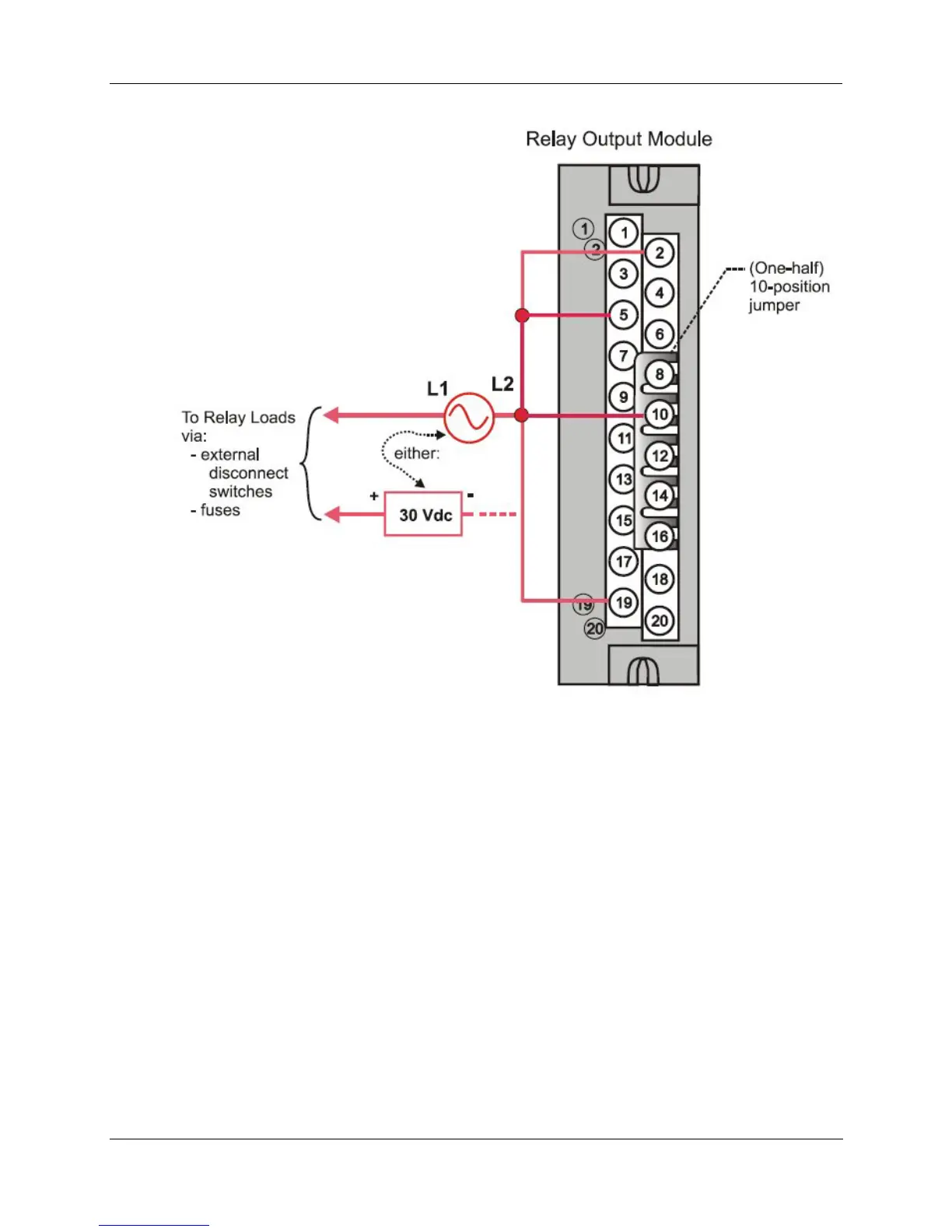
Figure 63 – Relay Output Module Jumpers
Pulse/Frequency/Quadrature Module Wiring (Figure 64 through Figure 70)
The 4 Channel Pulse/Frequency/Quadrature Module provides four different functionalities in the form of
Pulse Input, Frequency measurement, Quadrature encoder input and Pulse Output. Each of the 4 channels
can be configured for any one of these four functionalities; with the exception that quadrature encoder input
(A and B pulses) can be applied to only Channels 1 and 2 respectively. When configured for quadrature,
Channels 3 and 4 will still be available for use.
The Pulse Output functionality uses the digital output available on the module for outputting pulses.
Before installing be sure to set the module DIP switches for differential or single ended. See page 78.

 Loading...


