Components and Architecture - Hardware Components
24 HC900 Process Controller Installation and User Guide Revision 19
06/14
Redundancy Switch Module (C75 only)
The Redundancy Switch Module (RSM) is shown in Figure 13.
It sits between C75 controllers on rack. Left Controller is designated
“CPU-A”; right Controller is “CPU-B.” Features include:
1. Lead/Reserve controller status indicators.
2. Keyed switch for manual changes to controller modes or to facilitate a Manual
Fail Over.
Figure 13 – Redundancy Switch Module
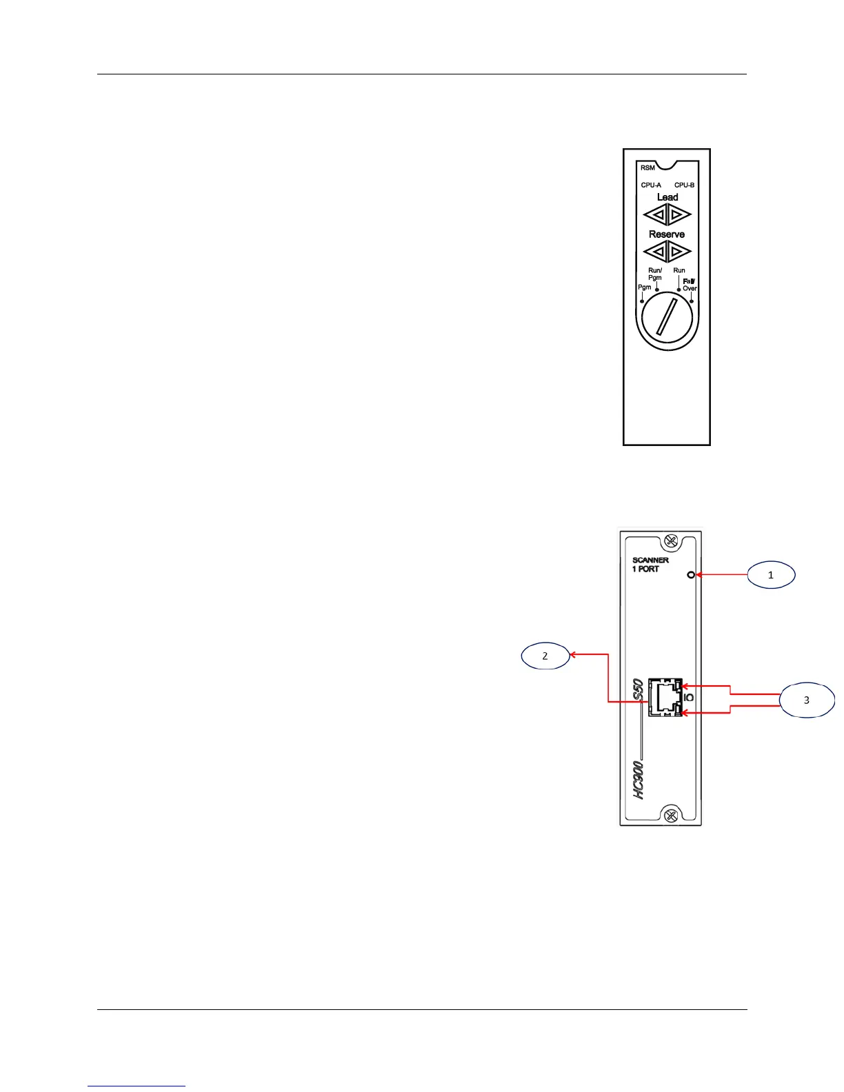
Scanner 1 Module (C50 and C50S/C70 and C70S only)
The Scanner 1 Module is shown in
Figure 14.
It sits in the I/O rack and provides the link between the
controller and remote I/O. Features at the front of the module
include:
1. LED status indicator for scanner functions.
2. One private Ethernet 10Base-T Port; connects to the I/O
expansion port on Controller Module (or to a port on a Switch
that connects to the Controller Module)
3. LED status/diagnostic indicators for communications
functions.
Figure 14 – Scanner 1 Module

 Loading...


