Appendix - Installation of Remote Termination Panels (RTPs) - Analog Input
Revision 19 HC900 Process Controller Installation and User Guide 211
06/14
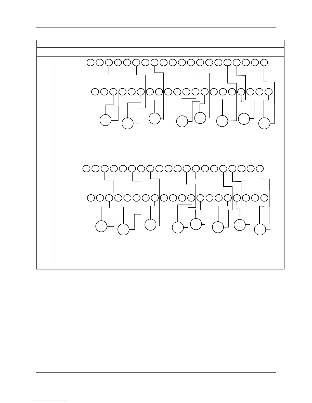
8 Point Analog Input
Step Action
1 2 3 7
8
94 5 6
10 11
12
13 17 18 1914
15 16 20
21
22 23
27 28
29
24 25
26
30 31 32 33 37 38 3934 35 36 40
+
-
+
-
+
-
+
-
+
-
+
-
mA
Input 1
mA
Input 2
mA
Input 3
mA
Input 4
mA
Input 5
mA
Input 6
mA
Input 7
-
+
mA
Input 8
+
-
Note: You must set
switches 1- 8 for Milliamp.
1 2 3 7
8
94 5 6
10
11 12
13 17 18 1914
15 16 20
21
22 23
27
28 29
24 25
26
30 31 32 33 37 38 3934 35 36 40
1 2 3
7
8 94 5
6
10 11
12 13 17 18 19
14
15 16 20
21 22
23
27 28
2924
25
26 30 31 32 33 37 38 3934 35 36 40
+
-
+
-
+
-
+
-
+
-
+
-
mA
Input 1
mA
Input 2
mA
Input 3
mA
Input 4
mA
Input 5
mA
Input 6
mA
Input 7
-
+
mA
Input 8
+
-
Note: You must set
switches 1- 8 for Milliamp.
Figure 95 – Milliamp input connections with 250 ohm shunt resistance
1 2 3 7 8 94
5 6 10 11 12 13 17 18 19
14 15 16 20
21 22 23 27 28 2924 25 26 30 31 32 33 37 38 39
34 35 36 40
+
-
+
-
+
-
+
-
+
-
+
-
V, mV
Input 1
V, mV
Input 2
V, mV
Input 3
V, mV
Input 4
V, mV
Input 5
V, mV
Input 6
V, mV
Input 7
-
+
V, mV
Input 8
+
-
Note:You must set
switches 1- 8
for Volts, Millivolts
1 2 3 7 8 94 5
6 10 11 12 13 17 18 1914
15 16 20
21 22 23 27 28 2924 25 26
30 31 32 33
37 38 3934 35 36
40
1 2 3 7 8 94
5 6 10 11 12 13 17 18 1914 15 16 20
21 22 23 27 28 29
24 25 26
30 31 32 33 37 38
3934 35 36 40
+
-
+
-
+
-
+
-
+
-
+
-
V, mV
Input 1
V, mV
Input 2
V, mV
Input 3
V, mV
Input 4
V, mV
Input 5
V, mV
Input 6
V, mV
Input 7
-
+
V, mV
Input 8
+
-
Note:You must set
switches 1- 8
for Volts, Millivolts
Figure 96 – Volt, millivolt input connections

 Loading...


