Diagnostics and Troubleshooting - Controller CPU indicators
Revision 19 HC900 Process Controller Installation and User Guide 163
06/14
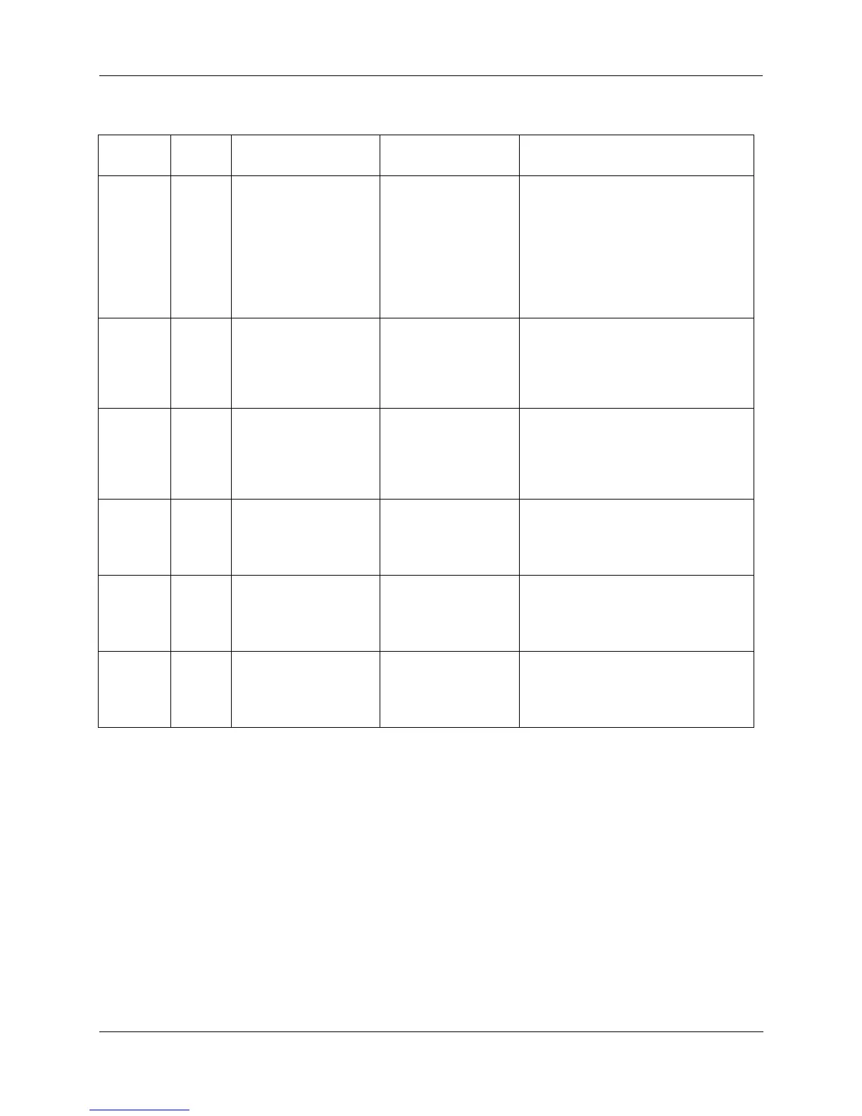
Table 26 – LED Indications on Controller CPUs
CPU
model
Figure
79 item
LED LED State/Color Description
All models 1 Controller Status Off
Solid Red
Blinking Yellow
Blinking Red
Solid Green
Blinking Green
Solid Yellow
No power.
Failed
Failed
(Diagnostic Code; refer to Table 27.)
PROGRAM Mode
RUN Mode
OFFLINE Mode
All models
2
For legacy systems,
RS-232/RS-485 S1 port
For new systems, RS-
485 S1 port
XMT/RCV
Yellow/Green
Yellow when transmitting, green when
receiving.
All models
3
For legacy systems,
RS-232/RS-485 S2 port
For new systems, RS-
485 S2 port
XMT/RCV
Yellow/Green
Yellow when transmitting, green when
receiving.
All models
4
5
E1 port
Upper LED
Lower LED
Yellow (On/Off)
Green (On/Off/Flash)
On for 100Base-T, Off for 10Base-T
On for connection, Off for no
connection, Flash for activity
C70
C75
6
7
E2 port
Upper LED
Lower LED
Yellow (On/Off)
Green (On/Off/Flash)
On for 100Base-T, Off for 10Base-T
On for connection, Off for no
connection, Flash for activity
C50
C70
C75
8
9
I/O port
Upper LED
Lower LED
Yellow (On/Off)
Green (On/Off/Flash)
On for 100Base-T, Off for 10Base-T
On for connection, Off for no
connection, Flash for activity

 Loading...


