Components and Architecture - Hardware Components
Revision 19 HC900 Process Controller Installation and User Guide 23
06/14
Controller Module
C30 and C30S, C50 and C50S, C70 and C70S, C75 Controllers share the same features, with exceptions
noted.
• CPU model number (C30 and C30S, C50 and C50S , C70 and C70S, C75).
• Lithium battery (beneath cover), which is readily accessible for field replacement.
• Mode switch (Pgm, Run/Pgm). Not present on C75; see RSM.
• Interfaces to PC
• For legacy systems, two serial ports, S1 and S2, each configurable as RS-232 or RS-485 interfaces to a
PC.
• For new systems, two serial RS-485 ports, S1 and S2 interfaces to PC using RS-485 to USB cable.
External modem or Modbus devices are interfaced using RS-485 to RS-232 converter. RS-485 interfaces
to PC, Operator Interface or Modbus devices/host.
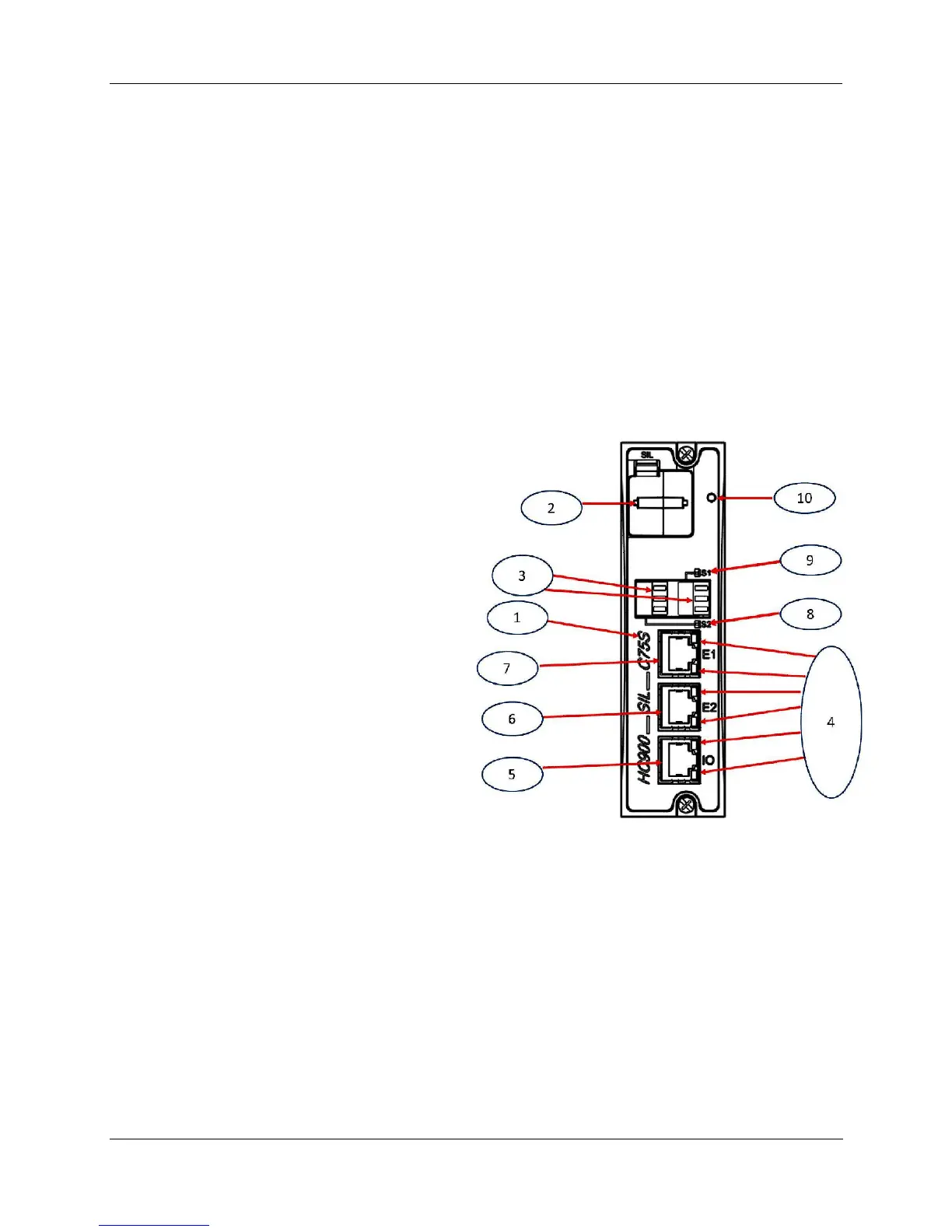
1. LED status indicators for communications
functions.
2. Connection to I/O port of Scanner Module.
C50 and C50S/C70 and C70S/C75 only.
3. Second Ethernet Host Connection to PC
applications or peer HC900 controllers.
C70/C75 only.
4. First Ethernet Host Connection to PC
applications or peer HC900 controllers.
5. LED status/diagnostic indicator for serial
port S2 (left).
6. LED status/diagnostic indicator for serial
port S1 (right).
7. LED status/diagnostic indicator for
controller module.
Figure 12 – Controller Module
Redundant controller rack contains two C75s. Left CPU is designated CPU-A, right CPU is CPU-B; either
CPU can be Lead.

 Loading...


