Appendix - Installation of Remote Termination Panels (RTPs) - Analog Input/Digital Input/Digital Output/Analog
Output
Revision 19 HC900 Process Controller Installation and User Guide 237
06/14
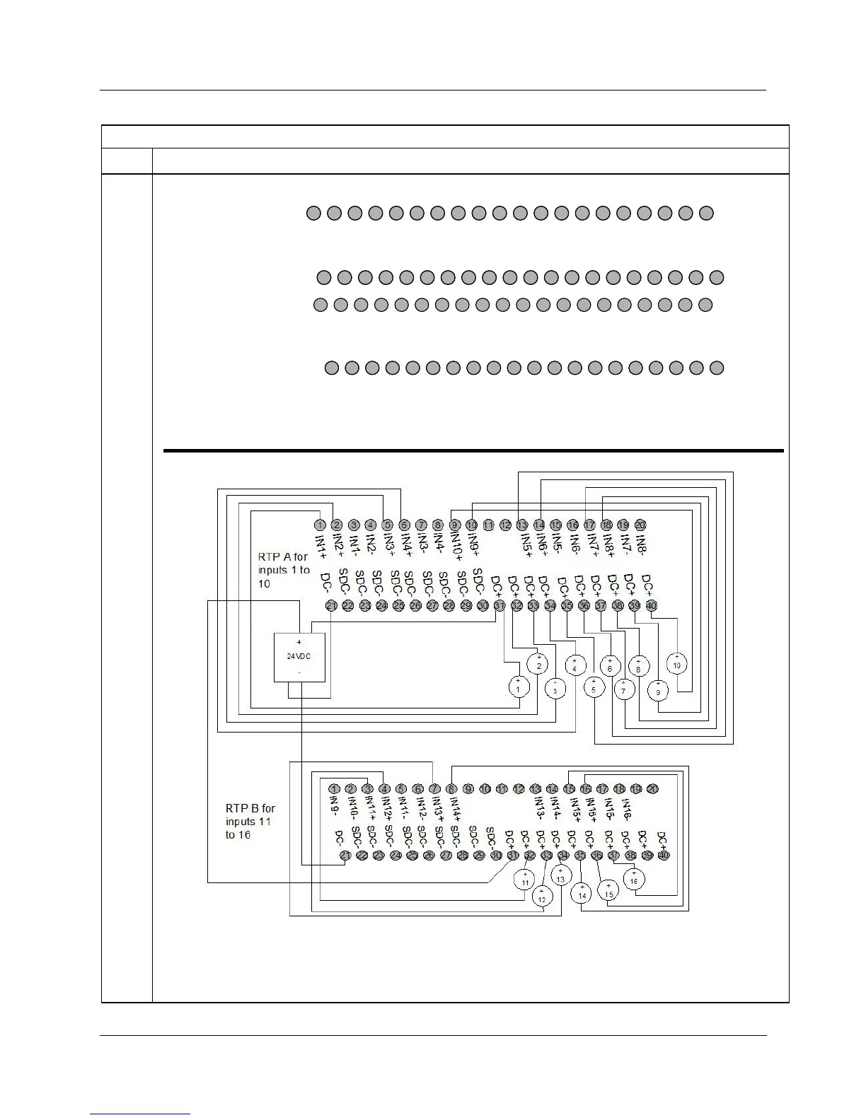
16 Point Analog Input
Step Action
4 Connect field wiring. Refer to the appropriate figure for your type of analog input.
21 22 23 24 25 26 27 28 29 30 31 32 33 34 35 36 37 38 39 4021 22 23 24 25 26 27 28 29 30 31 32 33 34 35 36 37 38 39 40
1 2 3 4 5 6
7
8 9 10 11 12 13 14 15 16 17 18 19 20
IN1+
IN5+
IN2+
IN3+
IN4+
IN6+
IN7+
IN9+
IN10+
IN8+
IN1
-
IN5
-
IN2
-
IN3
-
IN4
-
IN6
-
IN7
-
IN8
-
1 2 3 4 5 6
7
8 9 10 11 12 13 14 15 16 17 18 19 20
IN1+
IN5+
IN2+
IN3+
IN4+
IN6+
IN7+
IN9+
IN10+
IN8+
IN1
-
IN5
-
IN2
-
IN3
-
IN4
-
IN6
-
IN7
-
IN8
-
RTP A for
inputs 1 to 10
1 2 3 4 5 6 7 8 9 10 11 12 13 14 15 16 17 18 19 20
21 22 23 24 25
26 27 28 29 30 31
32 33 34 35 36 37 38 39 4021 22 23 24 25
26 27 28 29 30 31
32 33 34 35 36 37 38 39 40
IN11+
IN12+
IN13+
IN14+
IN11-
IN12-
IN15+
IN16+
IN15-
IN13-
IN14-
IN16-
IN15+
IN16+
IN15-
IN13-
IN14-
IN16-
IN9
-
IN10
-
RTP B for
inputs 9 to 16
Notice that Inputs 9 and 10 are connected across RTP A and RTP B.
Figure 100 Voltage input connections
Not shown: recommended external current loop fuses.
Additionally, on RTP A connect the following terminals: 3-22, 4-23, 7-24, 8-25, 15-26, 16-27, 19-29, 20-30
On RTP B connect the following terminals: 1-22, 2-23, 5-24, 6-25, 13-26, 14-27, 17-28, 18-29
Figure 101 Current connections with 2-wire transmitter

 Loading...


