Appendix - Installation of Remote Termination Panels (RTPs) - Analog Input/Digital Input/Digital Output/Analog
Output
236 HC900 Process Controller Installation and User Guide Revision 19
06/14
16 Point Analog Input
Step Action
2 Mount RTPs to DIN rail.
• Latch to rail. See page 244.
• Connect cables to RTPs. Cables are marked “RTP A” and “RTP B.” In step 4, RTP A will be wired to
Inputs 1-10, RTP B to Inputs 9-16. You can write on the RTPs’ labels to distinguish them.
• Note: Inputs 9 and 10 are wired between both RTPs.
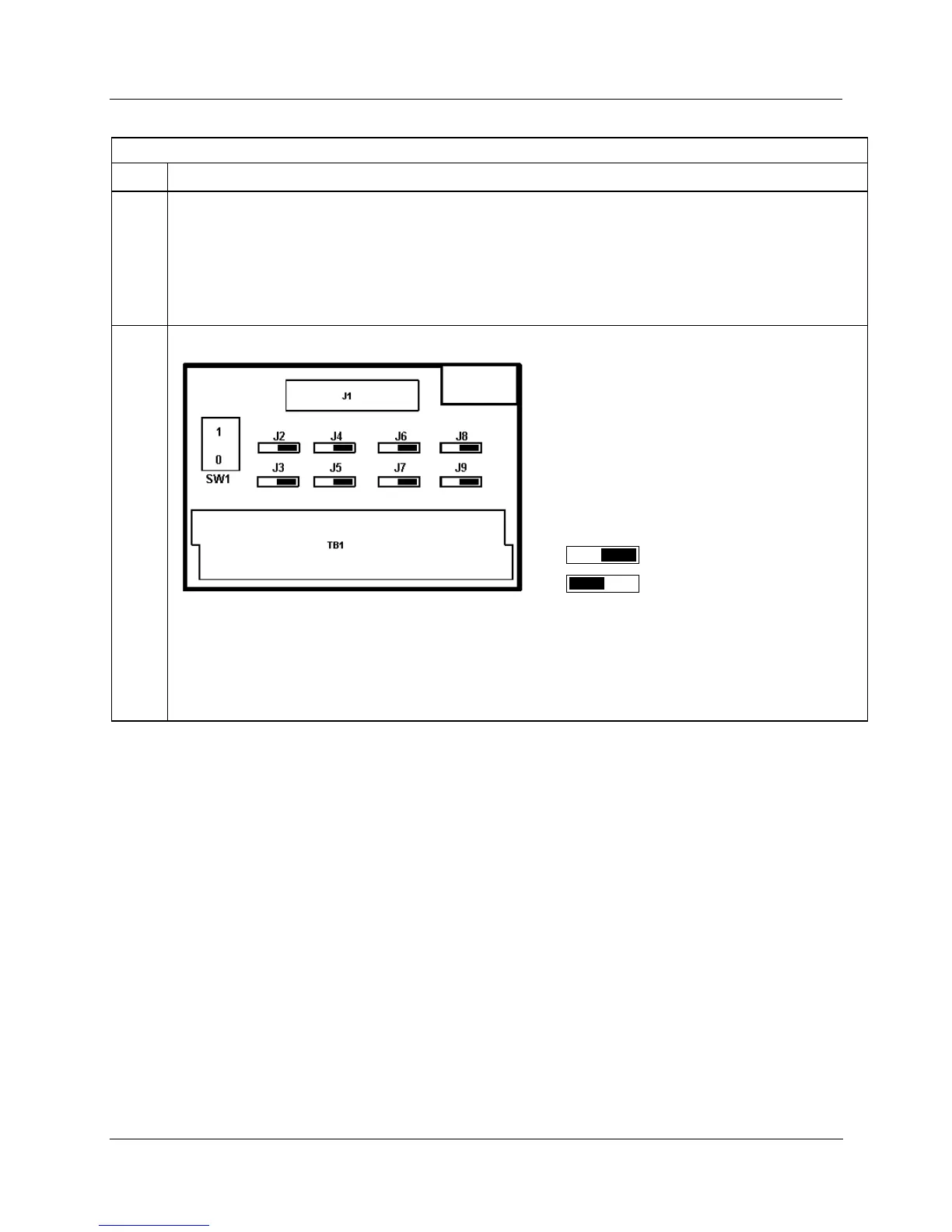
3 Set/verify jumper positions on each RTP as shown.
Module Removal / Insertion Under Power (RIUP) is supported by turning off Switch SW1 to allow removal of
the module from the rack without causing an arc. See page 73.
ATTENTION: SW1 opens current loop on the ground side so that RIUP of module is possible, but
voltage is still present on the positive side at RTP and module terminals.
See page 242 for RTP internal schematic.

 Loading...


