Rack Installation - Assemble I/O Expansion Racks
Revision 19 HC900 Process Controller Installation and User Guide 65
06/14
Step Procedure Comments/References
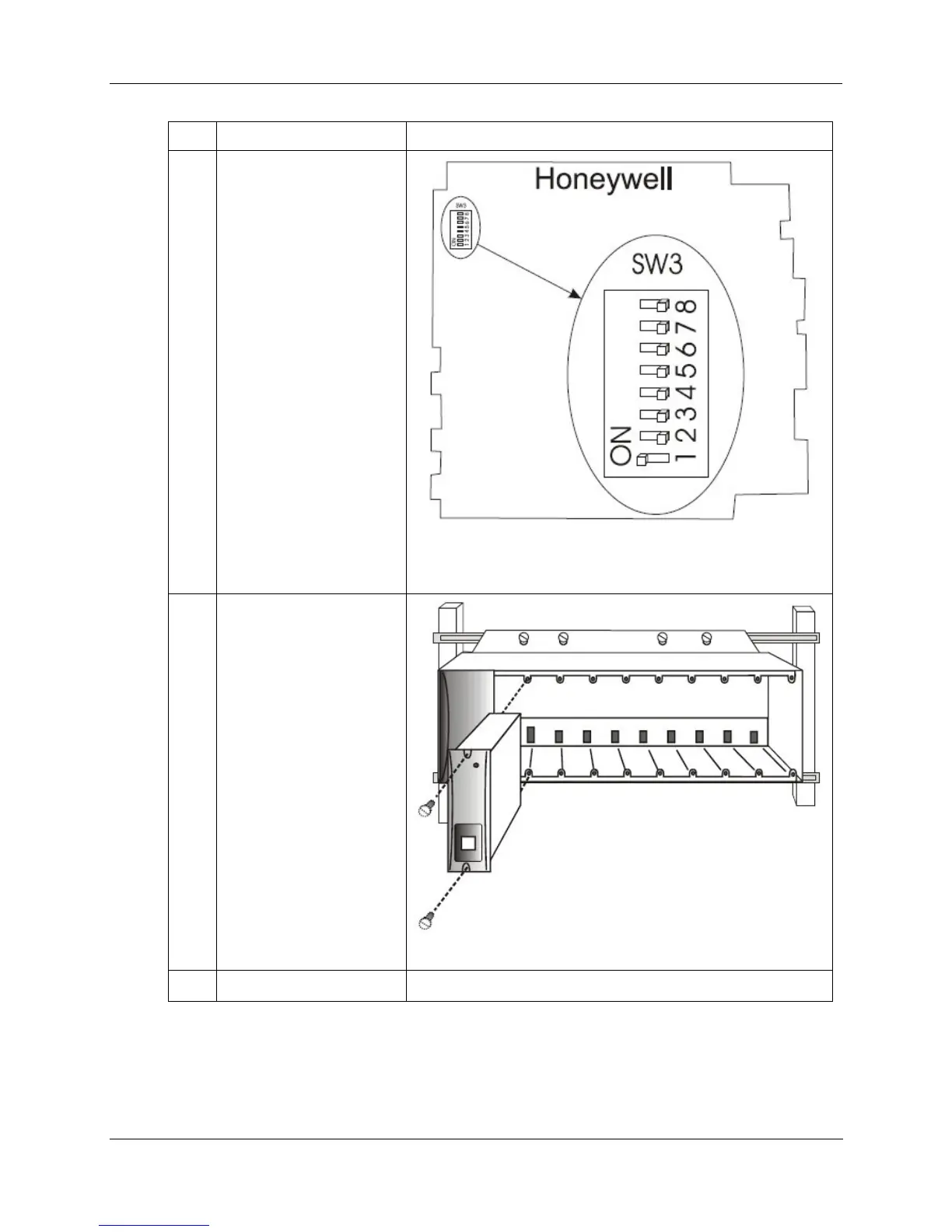
3 Set scanner address for
the I/O rack using the
Scanner Module DIP
switches on SW3 (shown
at right). For C50/C70, use
address 1-4. For C75, use
address 1-5.
DIP switches 6-8 must
be OFF. Only one DIP
switch may be ON:
DIP switch 1 ON =
Scanner 1
DIP switch 2 ON =
Scanner 2
DIP switch 3 ON =
Scanner 3
DIP switch 4 ON =
Scanner 4
DIP switch 5 ON =
Scanner 5
A small slotted screwdriver
or paperclip works well;
avoid pencils.
4
Repeat steps 1 through 3
for each I/O expansion
rack.
Then, for each I/O
expansion rack, insert the
Scanner Module
immediately to the right of
the Power Supply, and
secure it in place with the
two captured screws in the
faceplate.
5
I/O will be installed later. See Page 66.

 Loading...


