HT2000H_en_n.doc Page 168 of 167
FIGURE INDEX
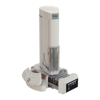
Figure 1: HT2000H/HT2000HT (tray open) top view 20
Figure 2: HT2000H/HT2000HT (tray closed) top view 20
Figure 3: HT2000H/HT2000HT 42 position rack 21
Figure 4: HT2000H Incubation oven 22
Figure 5: HT2000HT Incubation oven 24
Figure 6: Left location for incubation oven (bottom view) 24
Figure 7: Right location for incubation oven (bottom view) 24
Figure 8: Touch screen display 25
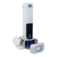
Figure 9: HT2100H top view 25
Figure 10: HT2100H 14 positions double fixed rack 26
Figure 11: HT2100H Incubation oven 27
Figure 12: Right location for rack 1B (bottom view) 27
Figure 13: Left location for rack 1B (bottom view) 27
Figure 14: Keypad (HT2100H) 28
Figure 15: Sliding lid down Figure 16: Sliding lid up 28
Figure 17: Syringe location 29
Figure 18: Syringe warmer assembly 30
Figure 19: Vial locator 30
Figure 20: “S” side of the plunger locker Figure 21: “B” side of the syringe locker
30
Figure 22: Connection panel 31
Figure 23: External power supply 32
Figure 24: Syringe pointer 33
Figure 25: Allen key 33
Figure 26: Tweezer_type 1 34
Figure 27: Tweezer_type 2 34
Figure 28: Screen type 1 35
Figure 29: Screen type 2_example A 35
Figure 30: Screen type 2_example B 35
Figure 31: Screen type 3_example A 40
Figure 32: Screen type 4 41
Figure 33: Screen type 5_example A Figure 34: Screen type 5_example B 41
Figure 35: Screen type 6_example A Figure 36: Screen type 6_example B 42
Figure 37: Open the box 44
Figure 38: Remove the cushions 44
Figure 39: Extract the autosampler from the box 44
Figure 40: Place the autosampler on a flat surface 45
Figure 41: Cut the adhesive tape 45
Figure 42: Remove the upper cushions 45
Figure 43: Remove the accessory boxes 46
Figure 44: Remove the cushions 46