Step 3 Disconnect cables from the faulty ATS main control box. Insulate each cable and
label it immediately after disconnecting it.
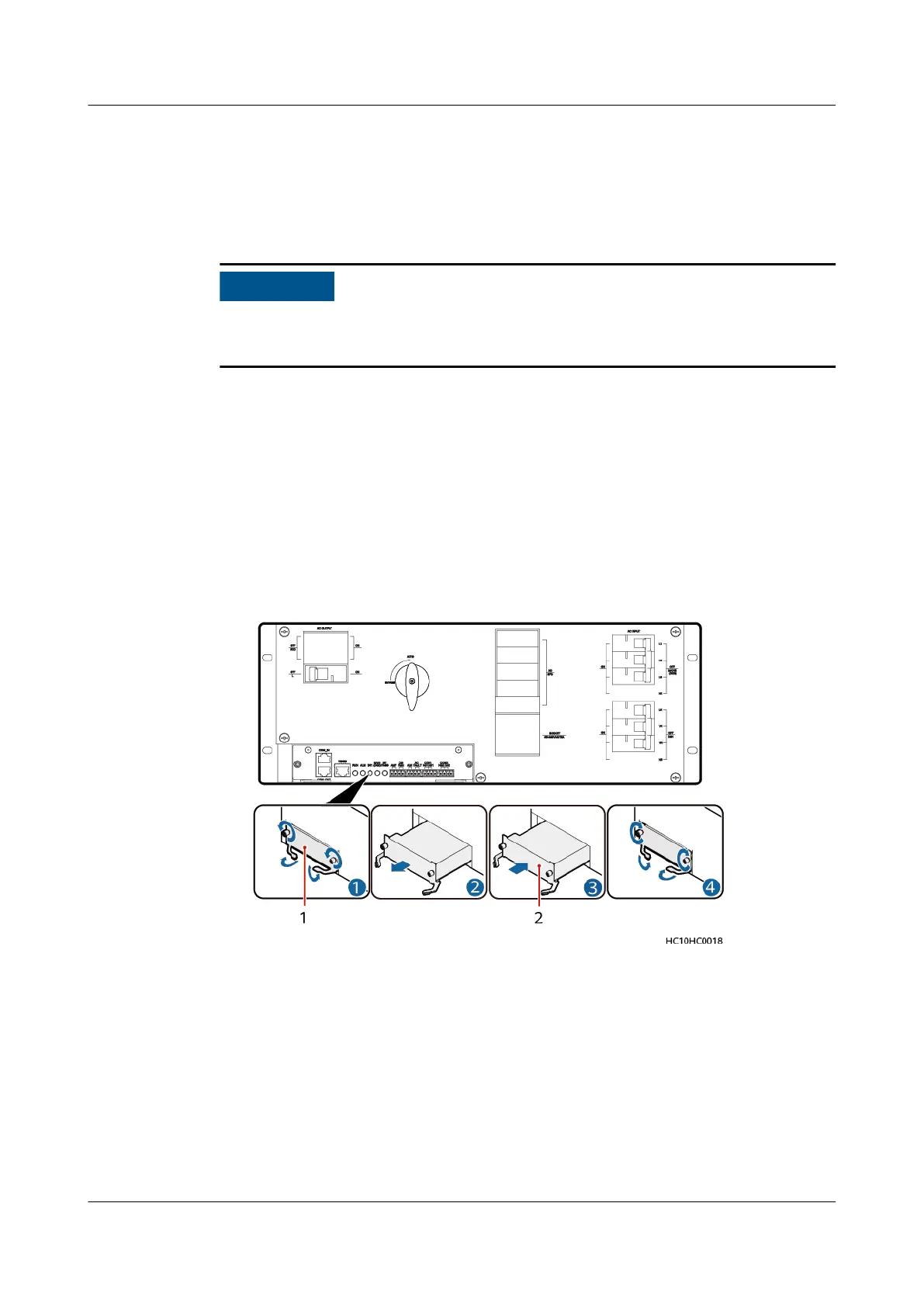
Step 4 Remove the faulty ATS main control box and install the replacement main control
box, as shown in the following gure.
If the ATS is at the end of CAN cascading, set a build-out resistor before installing
the replacement main control box.
1. Loosen the two captive screws on the panel of the faulty ATS main control
box using a screwdriver. Hold the ejector lever and pull out the faulty main
control box.
2. Hold the ejector lever of the replacement ATS main control box and insert the
main control box into the ATS subrack until its front panel aligns with that of
the ATS subrack.
3. Close the ejector lever.
4. Tighten the captive screws using a screwdriver.
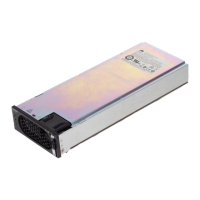
Figure 4-23 Replacing an ATS main control box
(1) Faulty ATS main control box
(2) Replacement ATS main control box
Step 5 Reconnect the cables to the replacement ATS main control box based on the cable
labels.
Step 6 Set parameters again according to the appropriate installation guide.
Step 7 Remove the ESD wrist strap or gloves and put all the tools away.
----End
iSitePower Integrated Smart Site (ICC1000-A1-E1)
User Manual 4 Maintenance
Issue 04 (2022-10-15) Copyright © Huawei Technologies Co., Ltd. 133