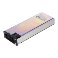
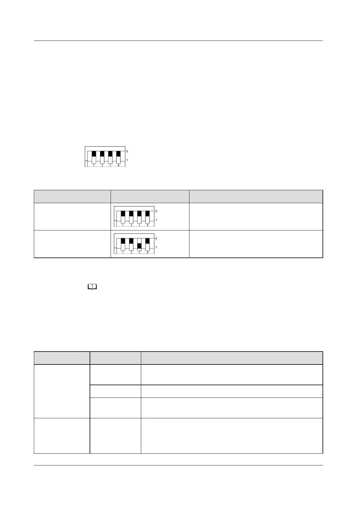
DIP Switch
The DIP switches are on the rear of the embedded power subrack and horizontally
placed and divided into two groups. Each group has four DIP switches, which are
DIP1, DIP2, DIP3, and DIP4 from left to right. A DIP switch is set to OFF when it is
ipped upward and to ON when it is ipped downward, as shown in Figure 3-44.
The digit 0 indicates OFF, and 1 indicates ON.
Figure 3-44 DIP switches
Table 3-44 Default settings
Item DIP Switch Setting Factory Default Value
First group of DIP
switches
0000
Second group of DIP
switches
0010
The two groups of DIP switches of the embedded power system are set by default before
delivery.
Indicator
Table 3-45 Indicator description
Indicator
Status Description
Power indicator Steady on
(Green)
There is DC input and the power system is working properly.
O There is no DC input.
Blinking
(green, 4 Hz)
There is DC input and the power system is loading software.
Fault indicator Steady on
(red)
SPD fault, industrial-frequency synchronization exception,
carrier synchronization exception, INV_BPS exception,
parallel CAN exception, hardware address exception, phase
address exception, or multi-host conict
iSitePower Integrated Smart Site (ICC1000-A1-E1)
User Manual 3 Components
Issue 04 (2022-10-15) Copyright © Huawei Technologies Co., Ltd. 66