(-'
(
(
Read/Write
Storage
Each
read/write
storage card contains 8K bytes
of
byte
addressable
read/write
storage. Since halfwords are
also addressed by some microinstructions, the storage is
organized so that the cards
K2,
L2,
M2, and N2 contain
the even bytes and
K4,
L4,
M4, and N4 contain the odd
bytes. The following
read/write
storage configurations
are allowed:
Storage
16K
32K
48K
64K
CAUTION
Cards
K2,
K4
Base
machine size
K2, K4,
L2,
L4
K2, K4,
L2,
L4,
M2,
M4
K2,
K4,
L2,
M2, M4, N2, N4
The machine must
be
powered down before you remove
or add
read/write
storage cards; otherwise, they can
be
damaged.
Defective
read/write
storage cards can sometimes
be
found by removing pairs
of
cards and observing
if
the
smaller configuration
is
free
of
the failure (see the
preceding caution).
Because the lowest 128 bytes
of
read/write
storage are
the registers and are contained on the controller
(G2)
card, the first
64
bytes
of
K2 and the first
64
bytes
of
K4 are not accessible and the machine might run error
free even
if
these bytes are defective.
Read/write storage is nondestructive; that is, data
is
not
changed
in
read/write
storage when read. When power
is turned on, data in
read/write
storage can be anything
and, in general, will not have correct parity. However,
the bring up program routine writes data into every
available byte
of
read/write
storage (including the
registers) so that
if
the bring up program runs
to
completion, every byte
of
read/write
storage has correct
parity
if it
is
not defective.
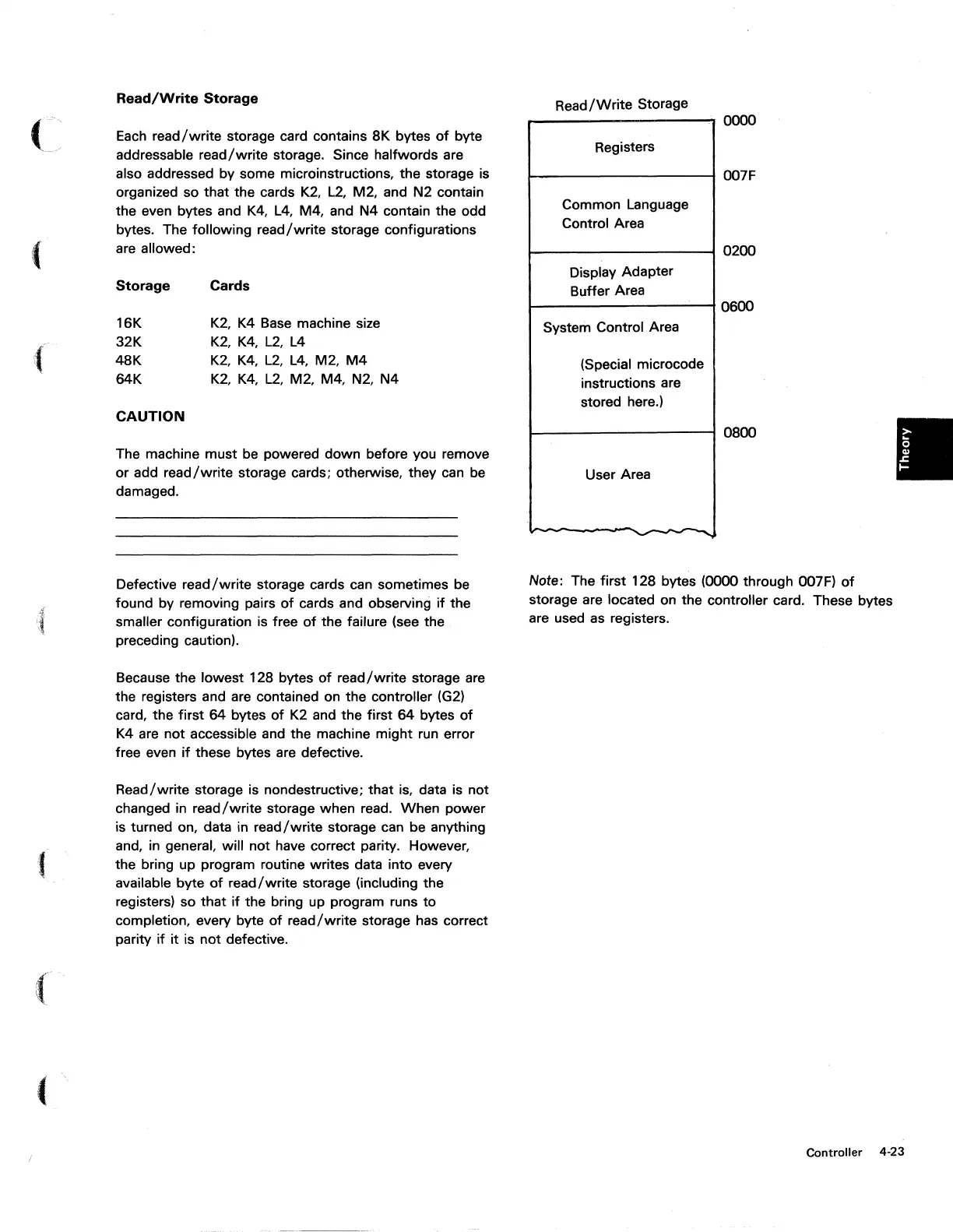
Read/Write
Storage
0000
Registers
oo7F
Common Language
Control Area
0200
Display Adapter
Buffer Area
0600
System Control Area
(Special microcode
instructions are
stored here.)
0800
User Area
......
-
.......
Note: The first 128 bytes (0000 through 007F)
of
storage are located on the controller card. These bytes
are used as registers.
Controller 4-23
 Loading...


