iSeries Model 570 149
Draft Document for Review October 18, 2004 5486m570.fm
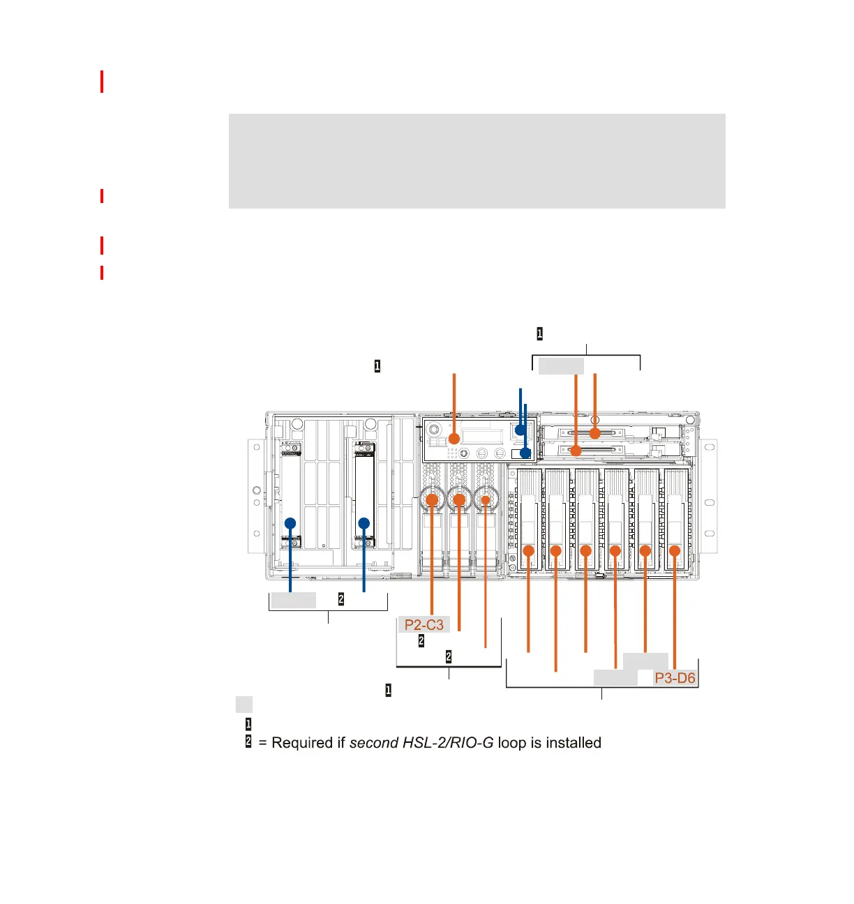
9406 Model 570 schematics
9406 Model 570 system unit front, rear, and top views
Note: The Model 570 system schematics are under construction at the time of
publication. The following diagrams show a view of the front, rear, and top of
the Model 570. You will find the latest diagrams with card slot placement
information in IBM Eserver iSeries and AS/400e System Builder,
SG24-2155, available on www.redbooks.ibm.com in June 2004.
P2-C1
P4-D2
P4-D1
P2-C2
P3-D1 P3-D5
P3-D2
P2-C5
P3-D3
P3-D4
P2-C4
DASD Six Pack
Processors
Operation Panel
( D1 Not supported
by i5/OS)
CPU Regulators
570 Front Locations
= Base
= Hot Plug Capable
USB
Ethernet
Slimline Media