WindO/I-NV4 User’s Manual 14-35
4 Using the Data
14
Data Log Function
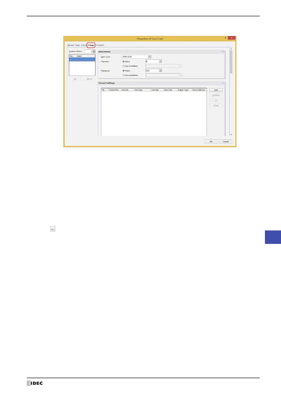
5 Click the Y-Axis tab.
6 Specify the number (1 to 4) of Y-axis in Number of Axes.
7 Selects the Y-axis for to configure in the (Y-Axis) and enters the name of the Y-axis.
The maximum number is 40 characters.
8 Click Add to add a channel to the list.
The total of all the Y-axis is 20 channels maximum.
9 Configures Channel No., Data No., Line Type, Line Size, Line Color and Trigger Type for the data to display on
the chart.
The channel number and the data number can be checked on the Data Log Settings dialog box.
When While ON is selected as Trigger Type, displays the graph when the value of device address is 1. Specifies the
bit device or the bit number of the word device in Device Address to serve as condition.
Click to display the Tag Editor. For the device address configuration procedure, refer to Chapter 2 “5.1 Device
Address Settings” on page 2-68.
The data to display in the chart is registered in the channel number (Ch1 to Ch20) for the chart selected in Channel
Settings.
10
Repeat steps 7 and 9 to register the data to display in the chart.
11
Click OK.
The Properties dialog box closes.
This concludes configuring the Line Chart.
 Loading...