WindO/I-NV4 User’s Manual 5-1
5
Screen
This chapter gives an overview of the MICRO/I screen and describes how to create setup and operate the screen.
1.1 Screen Types
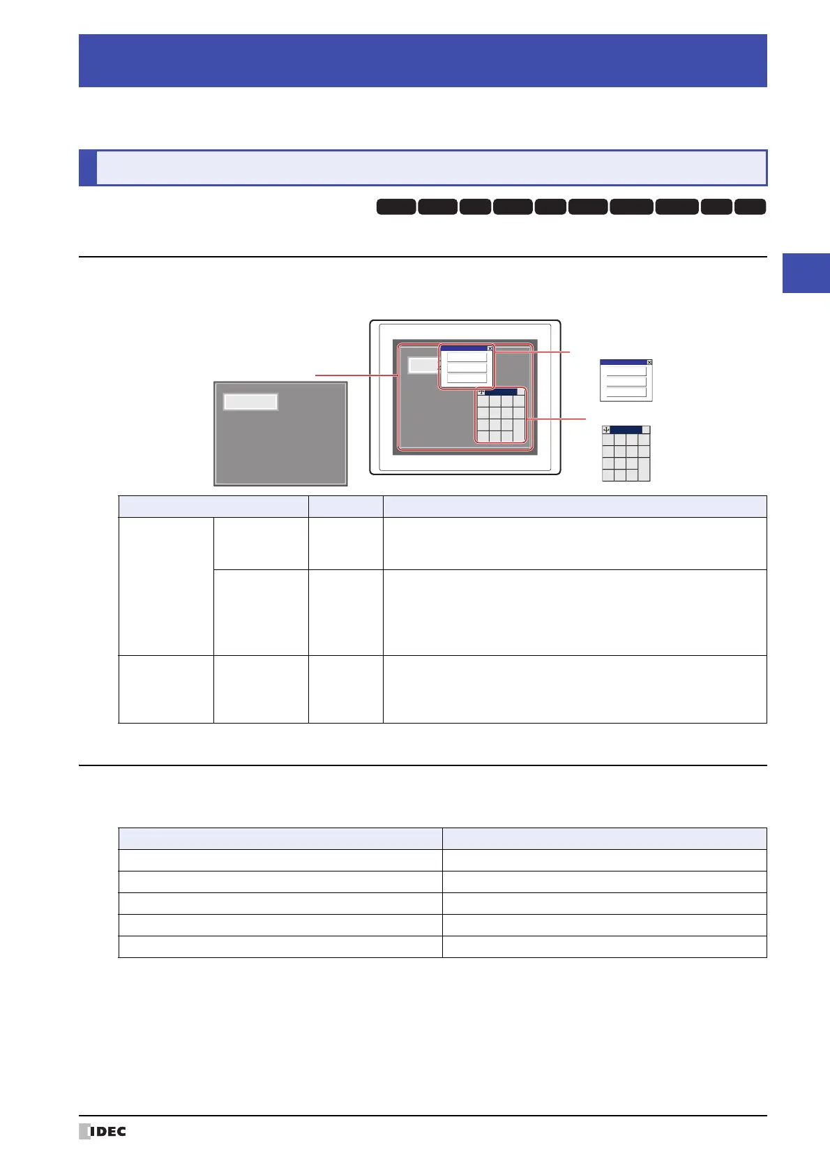
The types of screens offered by the MICRO/I and screens that can be created with the WindO/I-NV4 are given below.
1.2 Screen Size
The screen size differs depending on the MICRO/I model selected. The size of the MICRO/I screen is equal the size of
the Base Screen.
*1 The Keypad that is displayed when operating Numerical and Character Input parts when Standard is selected under Type
in the Keypad menu for Numerical and Character Input parts.
Chapter 5 Screen
1 Screen Overview
HG3G
HG2G-5FHG5G-V HG4G-V HG3G-V HG2G-V HG2G-5T
HG4G HG1G HG1P
Screen Type Screen No. Description
Screens that can
be created with
the WindO/I-NV4
Base Screen 1 to 3000
The screen that is displayed when the MICRO/I is in Run Mode. This
screen places drawing objects and parts on the base and creates a
screen that is displayed on the MICRO/I.
Popup Screen 1 to 3015
The Popup Screen that is displayed on the Base Screen when the
MICRO/I is in Run Mode. The size and coordinates of the screen can be
specified and this screen can also be moved on the Base Screen.
A Popup Screen for the standard Keypad
*1
will automatically be created
in screen numbers 3001 to 3015.
The screen
provided by the
MICRO/I
Maintenance
Screen
–
Using the screen that is displayed when the MICRO/I is in Run Mode,
you can switch from Run Mode to System Mode and load a screen to
adjust device monitor and screen brightness.
For details, refer to Chapter 34 “1 Maintenance Screen” on page 34-1.
MICRO/I
1230
1230
0
+
/
−
1
4
7
2
5
8
3
6
9
.
ENT
CLR
CAN
×
0
+
/
−
1
4
7
2
5
8
3
6
9
.
ENT
CLR
CAN
×
Maintenance
System Mode
Device Monitor
Adjust Brightness
Maintenance
System Mode
Device Monitor
Adjust Brightness
Base Screen
Popup Screen
Maintenance Screen
Model Screen Size (W x H)
HG5G/4G/3G-V 1024 x 768 dots
HG4G/3G 800 x 600 dots
HG2G-V, HG2G-5F 640 x 480 dots
HG2G-5T 320 x 240 dots
HG1G/1P 480 x 272 dots
 Loading...