5 User Communication
3-86 WindO/I-NV4 User’s Manual
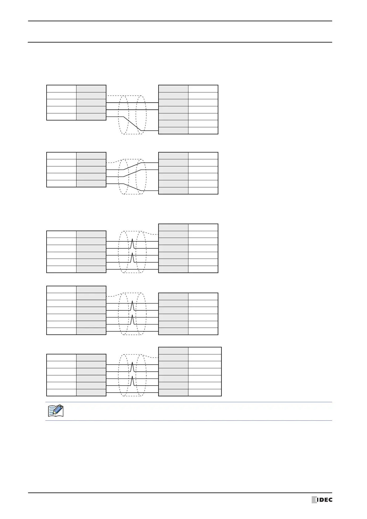
5.5 Connection Diagram for User Communication
When connecting an external device to the MICRO/I via user communication, refer to the following connection diagram.
■ Serial interface 1 (RS232C)
■ Serial interface 1 (RS422/485)
■ Serial Interface 2
HG5G/4G/3G/2G-V, HG4G/3G, HG2G-5F (Terminal)
Refer to the above “Serial interface 1 (RS232C)” and “Serial interface 1 (RS422/485)” about the connection diagram
of the Serial Interface 2 on the HG5G/4G/3G/2G-V, HG4G/3G, HG2G-5F.
Cover FG
Pin No. Name
3 SD
2 RD
7 RS
8 CS
-FG
Pin No.Name
-RD
-
SD
-SG
5 SG
Shield Wire
HG5G/4G/3G/2G-V,
HG4G/3G, HG2G-5F (Connector)
External Device (RS232C)
1 SD
Pin No. Name
2 RD
3 RS
4 CS
5 SG
-FG
Pin No.Name
-RD
-
SD
-SG
Shield Wire
HG5G/4G/3G/2G-V,
HG4G/3G, HG2G-5F/-5T, HG1G (Terminal)
External Device (RS232C)
Cover FG
Pin No. Name
1
RDB(RD
-
)
6
SDA(SD+)4
SDB(SD
-
)
9
Pin No.Name -
SDA -
SDB
-
RDA -
RDB -
SG
5 SG
RDA(RD+)
Shield Wire
HG5G/4G/3G/2G-V,
HG4G/3G, HG2G-5F (Connector)
External Device (RS422/485)
8 RDA(RD+)
Pin No. Name
9 RDB(RD
-
)
6 SDA(SD+)
7 SDB(SD
-
)
5 SG
-FG
Pin No.Name
-SDA
-SDB
-RDA
-RDB
-SG
Shield Wire
HG5G/4G/3G/2G-V,
HG4G/3G, HG2G-5F/-5T, HG1G (Terminal)
External Device (RS422/485)
1 FG
Pin No. Name
3
RDB
-
/TPI
-
2
SDA+/TPO+5
SDB
-
/TPO
-
4
Pin No.Name
-SDA
-SDB
-RDA
-RDB
-SG
6 SG
RDA+/TPI+
Shield Wire
HG1P (Connector)
External Device (RS422/485)
There is no pin number corresponding to TERM. When you need a terminating resistor, read the Chapter 1
"3 Important Points Regarding Wiring" in the WindO/I-NV4 External Device Setup Manual.
 Loading...