1 Communicating with the MICRO/I
24-8 WindO/I-NV4 User’s Manual
■ Search
Search for MICRO/I on the same network that can be connected to a computer via Ethernet communication.
Click this button to display the Search MICRO/I dialog box. For details, refer to “The Search MICRO/I dialog box” on
page 24-9.
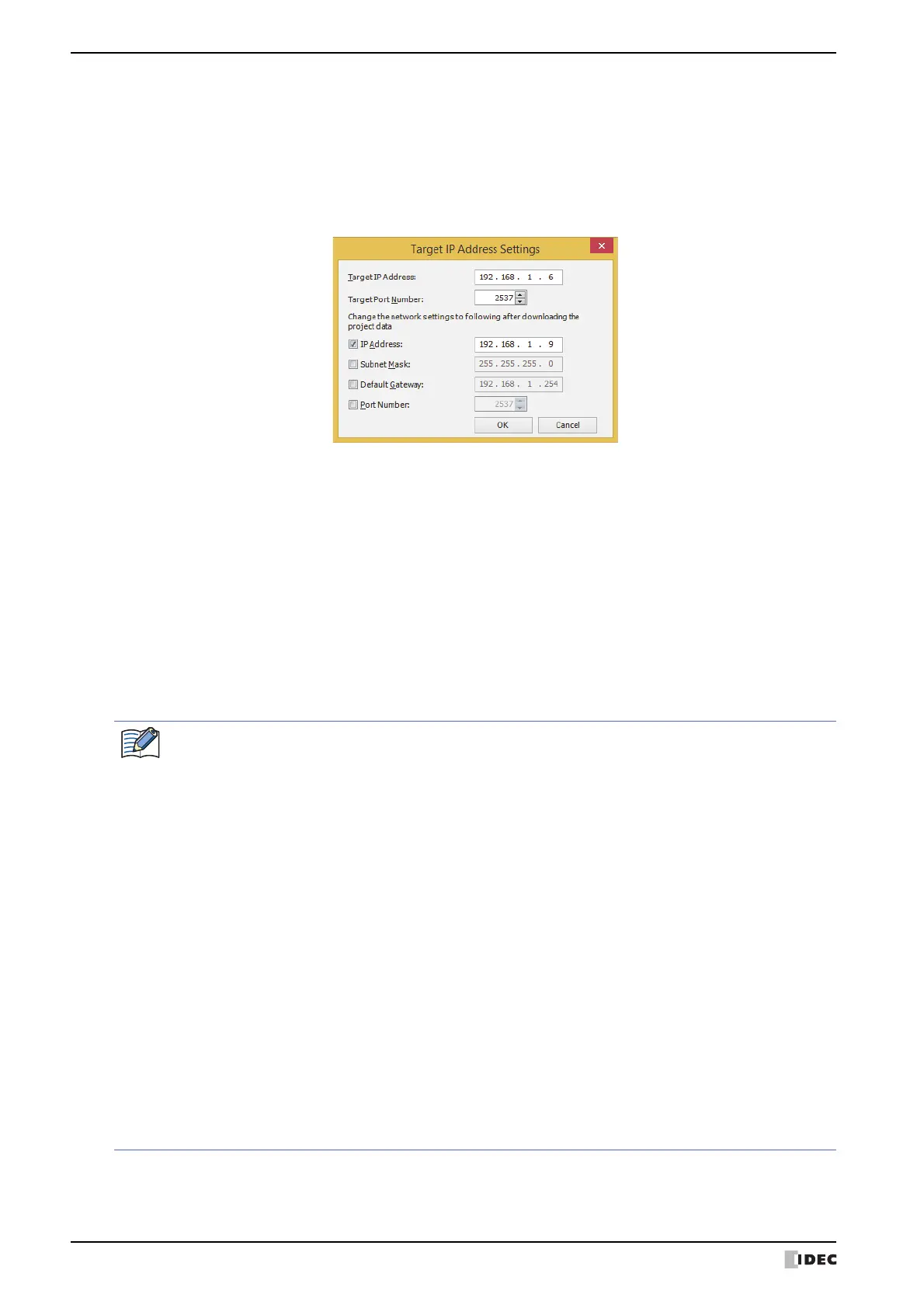
Target IP Address Settings dialog box
Specifies the IP address of the MICRO/I used for communication.
■ Target IP Address
Specify the IP address for the target MICRO/I to execute this function.
■ Target Port Number
Specify the port number for the target MICRO/I to execute this function.
■ Change the network settings to following after downloading the project data
Select the check boxes to change the Ethernet settings of the target MICRO/I after project data is downloaded.
IP Address:
Enter the IP address to register in the project data.
Subnet Mask: Enter the subnet mask to register in the project data.
Default Gateway: Enter the default gateway to register in the project data.
Port Number: Enter the port number to register in the project data.
Regarding TCP port number of MICRO/I, note the following points.
The numbers that cannot be used: • 2538 (for pass-through)
• 2101 (for FC4A Series MicroSmart direct connection pass-through)
Duplicate numbers cannot be configured in the following functions:
• Maintenance communication
( refer to Chapter 4 “Port Number” on page 4-40)
• Web server function
( refer to Chapter 4 “Port Number” on page 4-65)
•FTP server function
( refer to Chapter 4 “Port Number” on page 4-66)
• TCP Server is selected for the User Communication
( refer to Chapter 4 “Port No.” on page 4-42)
• Modbus as Manufacture and Modbus TCP Server as
Communication Driver are selected on the Communication
Driver tab
( refer to the WindO/I-NV4 External Device Setup Manual)
• YASKAWA Electric as Manufacture and MP2000(Ethernet) as
Communication Driver are selected on the Communication
Driver tab
( refer to the WindO/I-NV4 External Device Setup Manual)
 Loading...