3 HG2G-5T, HG1G
35-44 WindO/I-NV4 User’s Manual
3.4
External Interfaces
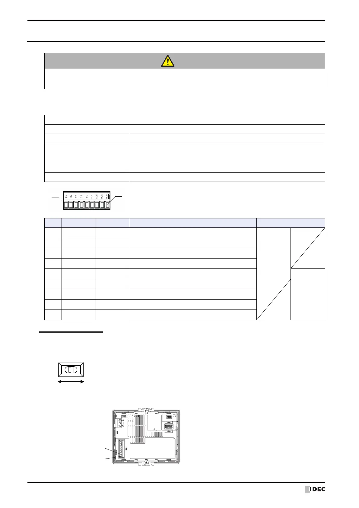
● Serial Interface
Use applicable cables for wiring and recommended ferrules (made by Phoenix Contact) as follows.
Using RS422/485 interface
• For HG2G-5T, if you set the Terminating Resistor Selector Switch to the ON side, this will connect the internal
terminating resistor (100Ω) between RDA and RDB.
Terminating Resistor Selector Switch
• HG1G is not equipped with terminating resistor. Insert a terminating resistor of an appropriate value (about 100 to
120 Ohm, 1/2 W minimum) between terminal number 8 (RDA) and terminal number 9 (RDB), if necessary.
CAUTION
Make sure to turn off the power to the HG2G-5T, HG1G before wiring each interface or switching the
terminating resistor selector switch.
Interface Specification RS232C, RS422/485
Connector Detachable Terminal Block 9-pin
Applicable cable AWG20 to AWG22
Recommended Pressure Terminal
AI 0,34-8 TQ
AI 0,5-8 WH
AI-TWIN 2 x 0,5-8 WH
(Phoenix Contact)
Tightening Torque 0.22 to 0.25 N·m
No. Name I/O Function Communication type
1SD OUT Send Data
RS232C
2 RD IN Receive Data
3 RS OUT Request to Send
4CS IN Clear to Send
5 SG - Signal Ground
RS422/485
6 SDA OUT Send Data (+)
7 SDB OUT Send Data (-)
8 RDA IN Receive Data (+)
9 RDB IN Receive Data (-)
Terminal Number 8 (RDA)
Terminal Number 9 (RDB)
 Loading...