3 Project Settings Dialog Box
4-28 WindO/I-NV4 User’s Manual
■ Watch Dog
Select this check box to monitor on the external device side whether or not the MICRO/I and the external device are
communicating by writing a set value (00FF (Hex)) at a fixed interval.
■ Disable Switch
Select this check box to enable and disable touch switches with a value of device address.
Touch switches are enabled when the value of device address is 1. They are disabled when the device value is 0.
■ Use Device Cache
Select this check box to execute processing by reading all the values of the external device addresses configured for a
screen when switching the base screen or when displaying a popup screen.
■ Start Part with synchronous
Select this check box to operate commands and HMI Special Internal Relays LSM1, LSM2, LSM3, and LSM5 after
reading all the values of the external device addresses configured on the screen.
When this check box is cleared, all processing is immediately executed when the screen is displayed.
■ Start from 0 in Always Entry Mode of Numerical Input
Select this check box to display 0 when a Numerical Input that has the Always Entry Mode check box selected on
the General tab is displayed on the screen. When this check box is cleared, the value of device address is displayed.
This option is reflected for all Numerical Inputs configured in the project.
■ Storage Method of String Data
Selects the handling method for text entered with the Character Input and values of device addresses read by the
Message Display.
Device Address: Specifies the word device to write the value.
Click to display the Tag Editor. For the device address configuration procedure, refer to Chapter
2 “5.1 Device Address Settings” on page 2-68.
Time (sec): Specifies the interval to write the value (1 to 65535).
Device Address: Specifies the bit device or the bit number of the word device that is read to enable or disable touch
switches.
Click to display the Tag Editor. For the device address configuration procedure, refer to Chapter
2 “5.1 Device Address Settings” on page 2-68.
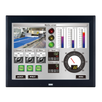
from Upper byte: Values of device addresses are read from and written to the upper order byte.
Example: When the text ABCDE is entered with the Character Input and written to the
destination device address LDR100
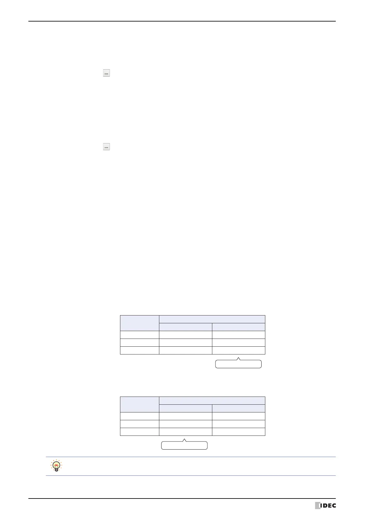
from Lower byte: Values of device addresses are read from and written to the lower order byte.
Example: When the text ABCDE is entered with the Character Input and written to the
destination device address LDR100
Device address
Stored value
Upper byte Lower byte
LDR100 'A' = 41 (Hex) 'B' = 42 (Hex)
LDR101 'C' = 43 (Hex) 'D' = 44 (Hex)
LDR102 'E' = 45 (Hex) 0
NULL terminang character
Device address
Stored value
Upper byte Lower byte
LDR100 'B' = 42 (Hex) 'A' = 41 (Hex)
LDR101 'D' = 44 (Hex) 'C' = 43 (Hex)
LDR102 0 'E' = 45 (Hex)
NULL terminang character
When handling strings, 0 is written to the device address as the NULL terminating character and treated as
the end of the string.
 Loading...