10–11
Transpector CPM Operating Manual
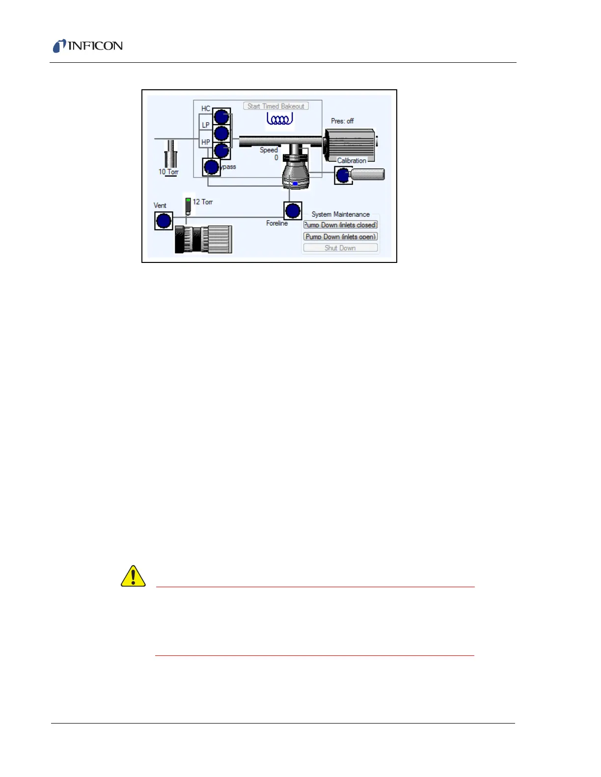
Figure 10-18 Configuration monitor window illustration
Determine which valve to open.
V1 (LP) —low pressure valve
V2 (HP) —high pressure valve (tied to V4, the bypass valve)
V3 (HC) —high conductance valve (used if the sensor’s process
connection is under high vacuum)
V4 (Bypass)—bypass valve (used in conjunction with V2)
V5 (Calibration) —calibration valve (available if a calibration gas is
installed)
To open the valve, click on the Valve Status indicator in the CPM figure at
the bottom of the screen. The Valve Status indicator will switch from dark
blue to green.
8 Click Start Configuration Monitor. The sensor will begin collecting data with
the configuration set up using the chosen data acquisition parameters.
9 If the data is satisfactory, log the parameters and save the configuration. Use
these data acquisition parameters in any data collection method.
10 If the data is unsatisfactory, repeat this procedure with different parameters.
CIS Pressure (Torr) is calibrated in the factory at
40 eV electron energy at 200 µA emission current.
Changing electron energy and/or emission current will
cause incorrect CIS pressure readings.