Multitron - Incubation Shaker
Setup and Function
Page 32 of 146 25 February 2019
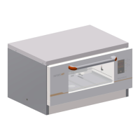
High base, 41 cm
Individual units and equipment stacked in pairs can be fitted with a
41 cm base. The base has an adjustable foot that can be used to
level the equipment.
The interior of the high base can be used as a storage space, e.g.
for trays that are currently not in use. Alternatively, a suitable cool-
ing unit is available as an option for the high base.
3.7 Operating and Indicating Elements
3.7.1 Main Switch
The main switch is located on the right-hand side of the equipment.
As soon as the equipment is switched on, the main
green. In addition to normal switching on and off, the main switch
also works as an emergency switch.
In case of an emergency shut down via the main switch, all pa-
rameter setpoints are stored and the equipment restarts immedi-
ately when it is switched on via the main switch.
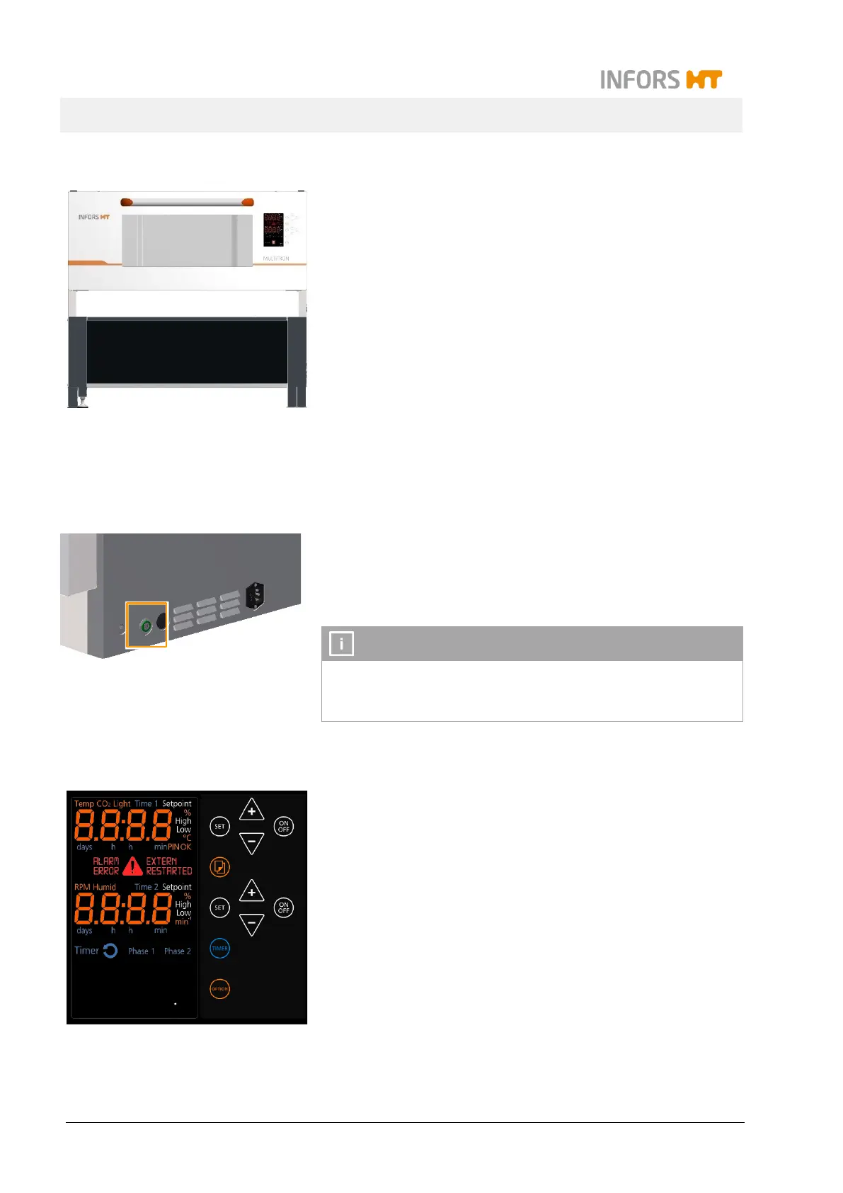
3.7.2 Operating Panel
All equipment functions can be controlled directly via the operating
panel on the front of the unit. The operating panel is divided into
display and operating sections:
In the display section on the left side, information on actual
values and setpoints, runtimes of the timer function and fault
notifications are displayed, among other things.
The keys in the operating section on the right side can be
used to set the parameters and the timer function and adjust
the basic settings of the equipment.
For detailed information on the display and operating elements
chapter 7.3 "Overview about the Display und Controls", page 76.