Multitron - Incubation Shaker
Options
25 February 2019 Page 47 of 146
4.8.2 Connection Assignment
The connections of the output module are assigned as follows:
nel
0 °C to 100 °C = 4 mA to 20 mA
0 °C to 100 °C = 4 mA to 20 mA
25/50 mm throw: 0 min
1
to 500 min
1
= 4 mA to 20 mA
3 mm throw: 0 min
1
to 1000 min
1
= 4 mA to 20 mA
4 Iout3 / AGND3/4 Speed setpoint 25/50 mm throw: 0 min
1
to 500 min
1
= 4 mA to 20 mA
3 mm throw: 0 min
1
to 1000 min
1
= 4 mA to 20 mA
2
0 % to 20 % = 4 mA to 20 mA
2
0 % to 20 % = 4 mA to 20 mA
0 % to 100 % = 4 mA to 20 mA
8 Iout7 / AGND6/7 Humidity setpoint 0 % to 100 % = 4 mA to 20 mA
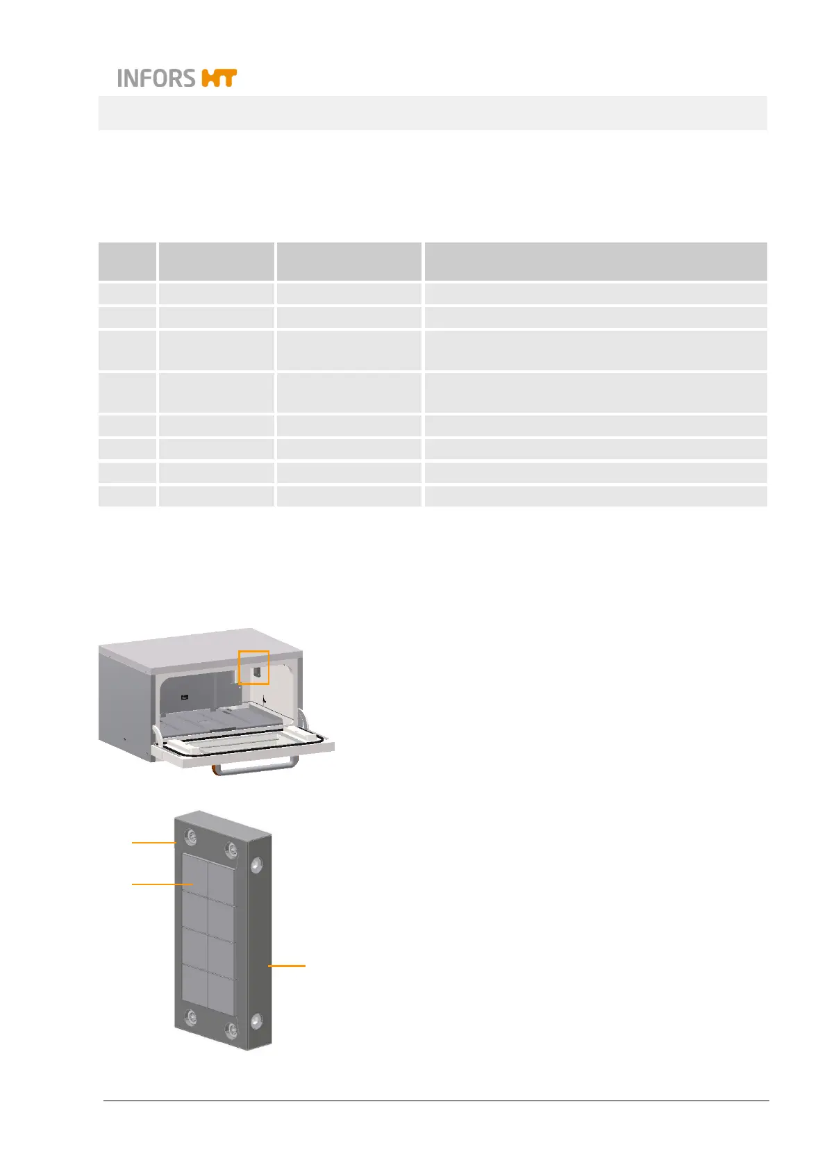
4.9 Cable Pass-through
4.9.1 Setup and Function
A pass-through for cables or hoses can be installed on the right
side of the casing. This can be used to guide additional sensors or
gassing into the incubation chamber.
The pass-through reduces loss of heat and/or humidity and, if ap-
plicable, gas consumption if cables or hoses have to be passed
into the incubation chamber.
The cable pass-through consists of a dividable cable-pass-through
bar (1) into which slotted sealing elements (cable sleeves) (2) can
be inserted. The cables are affixed and strain-relieved using cable
sleeves. Openings that are not required are sealed using a dummy
sleeve. The cable pass-through is screwed onto the inside of the
casing. A suitable screw driver (SW 4) is included to dismantle the
removable part of the cable pass-through bar (3).
1
2
3